
Page 193 - Design of Solar Thermal Power Plants
P. 193
178 3. GENERAL DESIGN OF A SOLAR THERMAL POWER PLANT
as the reference when implementing smoothing processing toward
the predicted outlet temperature data of heat-transfer fluid within the
parabolic trough collector.
In order to clearly express the prediction results, difference between
the measured and the predicted outlet temperatures of heat-transfer fluid
within the parabolic trough collector is offered as the absolute error, and
used to divide the measured outlet temperature of heat-transfer fluid
within the parabolic trough collector in order to obtain the ratio that can
be used as the relative error of prediction results.
Furthermore, in order to demonstrate the working effect of the
collector, it is also necessary to calculate the collector efficiency,
which refers to the ratio of the output energy from parabolic trough
collector to the solar DNI projected into the concentration field dur-
ing operation. Equation in ASHRAE 93 standard is applied in this
book, and solar irradiance G bp that considers the cosine effect is
selected as the denominator of efficiency calculation equation of energy
projected into the concentration field, which is shown in Eq. (3.74).
There is also some literature that has only applied solar direct normal
irradiation G DN as the denominator of the efficiency equation without
considering the influence of cosine loss.
_
R
c oil mðT fo T fi Þds
h ¼ R (3.74)
A a G bp ds
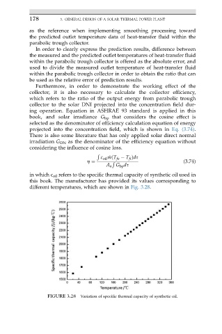
in which c oil refers to the specific thermal capacity of synthetic oil used in
this book. The manufacturer has provided its values corresponding to
different temperatures, which are shown in Fig. 3.28.
FIGURE 3.28 Variation of specific thermal capacity of synthetic oil.