
Page 90 - Designing Sociable Robots
P. 90
breazeal-79017 book March 18, 2002 14:2
The Vision System 71
20
18
16
14
Pixel disparity 12 8
10
6
4
2
0
0 2 4 6 8 10 12 14 16
Time (seconds)
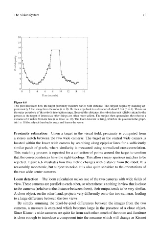
Figure 6.6
This plot illustrates how the target proximity measure varies with distance. The subject begins by standing ap-
proximately 2 feet away from the robot (t = 0). He then steps back to a distance of about 7 feet (t = 4). This is on
the outer periphery of the robot’s interaction range. Beyond this distance, the robot does not reliably attend to the
person as the target of interest as other things are often more salient. The subject then approaches the robot to a
distance of 3 inches from its face (t = 8to t = 10). The loom detector is firing, which is the plateau in the graph.
At t = 10 the subject then backs away and leaves the scene.
Proximity estimation Given a target in the visual field, proximity is computed from
a stereo match between the two wide cameras. The target in the central wide camera is
located within the lower wide camera by searching along epipolar lines for a sufficiently
similar patch of pixels, where similarity is measured using normalized cross-correlation.
This matching process is repeated for a collection of points around the target to confirm
that the correspondences have the right topology. This allows many spurious matches to be
rejected. Figure 6.6 illustrates how this metric changes with distance from the robot. It is
reasonably monotonic, but subject to noise. It is also quite sensitive to the orientations of
the two wide center cameras.
Loom detection The loom calculation makes use of the two cameras with wide fields of
view. These cameras are parallel to each other, so when there is nothing in view that is close
to the cameras (relative to the distance between them), their output tends to be very similar.
A close object, on the other hand, projects very differently on to the two cameras, leading
to a large difference between the two views.
By simply summing the pixel-by-pixel differences between the images from the two
cameras, a measure is extracted which becomes large in the presence of a close object.
Since Kismet’s wide cameras are quite far from each other, much of the room and furniture
is close enough to introduce a component into the measure which will change as Kismet