
Page 39 - Digital Analysis of Remotely Sensed Imagery
P. 39
12 Cha pte r O n e
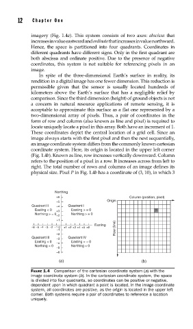
imagery (Fig. 1.4a). This system consists of two axes: abscissa that
increases in value eastward and ordinate that increases in value northward.
Hence, the space is partitioned into four quadrants. Coordinates in
different quadrants have different signs. Only in the first quadrant are
both abscissa and ordinate positive. Due to the presence of negative
coordinates, this system is not suitable for referencing pixels in an
image.
In spite of the three-dimensional Earth’s surface in reality, its
rendition in a digital image has one fewer dimension. This reduction is
permissible given that the sensor is usually located hundreds of
kilometers above the Earth’s surface that has a negligible relief by
comparison. Since the third dimension (height) of ground objects is not
a concern in natural resource applications of remote sensing, it is
acceptable to approximate this surface as a flat one represented by a
two-dimensional array of pixels. Thus, a pair of coordinates in the
form of row and column (also known as line and pixel) is required to
locate uniquely locate a pixel in this array. Both have an increment of 1.
These coordinates depict the central location of a grid cell. Since an
image always starts with the first pixel and then the next sequentially,
an image coordinate system differs from the commonly known cartesian
coordinate system. Here, its origin is located in the upper left corner
(Fig. 1.4b). Known as line, row increases vertically downward. Column
refers to the position of a pixel in a row. It increases across from left to
right. The total number of rows and columns of an image defines its
physical size. Pixel P in Fig. 1.4b has a coordinate of (3, 10), in which 3
Northing
+6 Column (position, pixel)
Origin
+5
Quadrant II +4 Quadrant I
Easting < 0 +3 Easting > = 0 P
Northing > = 0 +2 Northing > = 0
+1
Easting
–6 –5 –4 –3 –2 –1 0 +1 +2 +3 +4 +5 +6 Row (line)
–1
–2
Quadrant III –3 Quadrant IV
Easting < 0 Easting > = 0
–4
Northing < 0 Northing < 0
–5
–6
(a) (b)
FIGURE 1.4 Comparison of the cartesian coordinate system (a) with the
image coordinate system (b). In the cartesian coordinate system, the space
is divided into four quadrants, so coordinates can be positive or negative,
dependent upon in which quadrant a point is located. In the image coordinate
system, all coordinates are positive, as the origin is located in the upper left
corner. Both systems require a pair of coordinates to reference a location
uniquely.