
Page 104 - Dust Explosions in the Process Industries
P. 104
Dust Explosions: An Overview 77
1.4.4.4
Passive Devices for Interrupting Dust Explosions in Ducts
The device illustrated in Figure 1.82 was described relatively early by Scholl et al.
(1979) and subsequently by others.
BURSTING DISK
-/-OR OTHER VENT COVER
Figure 1.82 Section through device for interrupt-
ing dust explosions in ducts by combining change
of flow direction and venting. Flow direction may
also be opposite to that indicated by arrows.
The basic principle is that the explosion is vented at a point where the flow direction
is changed by 180". Due to the inertia of the fast flow caused by the explosion, the flow
tends to maintain its direction rather than making a 180" turn. However, the boundaries
for the applicability of the principle have not been fully explored. Parameters that may
influence performance include the explosion properties of dusts, velocity of flame enter-
ing the device, direction of flame propagation, and direction, velocity, and pressure of
initial flow in duct. Faber (1989) proposed a simplified theoretical analysis of the system
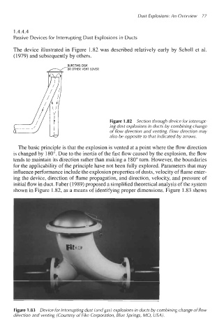
shown in Figure 1.82, as a means of identifying proper dimensions. Figure 1.83 shows
Figure 1.83 Device for interrupting dust (and gas) explosions in ducts by combining change of flow
direction and venting (Courtesy of Fike Corporation, Blue Springs, MO, USA).