
Page 109 - Dust Explosions in the Process Industries
P. 109
82 Dust Explosions in the Process Industries
cases, it is preferred to make the process apparatus in which the primary explosion
occurs so strong that it can withstand the full maximum explosion pressure under adia-
batic, constant volume conditions. Such pressures are typically in the range 5-12 bar(g)
(see Table A1 in the Appendix. See also Sections 9.3.7.2 and 9.3.7.7 in Chapter 9.)
1.4.5.2
The “Explosion Strength” of a Process Unit
The development of a stringentphilosophy for the design of process equipment that has
to withstand dust explosions is to a large extent due to the work of Donat (1978, 1984).
More recent summaries of the subject were given by Kirby and Siwek (1986), Pasman
and van Wingerden (1988) and Margraf and Donat (1989).
Donat (1978) introduced the useful distinctionbetween pressure-resistantdesign and
pressure-shock-resistantdesign. The first applies to pressure vessels that must be capa-
ble of withstanding the maximum permissiblepressure for long periods without becoming
permanently deformed. In principle, this concept could be used to design explosion-
resistant equipment, by requiring that the process unit be designed as a pressure vessel
for a maximum permissible working pressure equal to the maximum explosion pressure
to be expected.However, experiencehas shown that this is a very conservativeand expen-
sive design. Pressure-shock-resistantdesign means that the explosionis permitted to cause
slight permanent deformationof the process unit, as long as the unit does not rupture. This
means that, for a given expected maximum explosion pressure, a considerablyless heavy
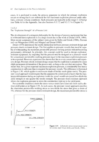
constructionis sufficient than is required for pressure vessels. The differenceis illustrated
in Figure 1.91,which applies to enclosures made of ferritic steels (plate steels). The pres-
sure vessel approach would require that the apparatusbe constructed so heavy that the max-
imum deformation during an explosion inside the vessel would not exceed two-thirds the
yield strength or one-quarter the tensile strength. The pressure-shock-resistant approach
allows the explosion pressure to stress the construction right up to the yield point.
For austenitic(stainless)steels the stress-versus-straincurve does not show such a dis-
tinct yield point as in Figure 1.91. In such cases, the pressure vessel approach specifies
the maximum permissible working stress as two-thirds the stress that gives a strain of
1%, whereas for the pressure-shock-resistantdesign, the maximum permissible stress is
YIELD STRENGTH
---_-_- __-_
1/4 x TENS. STRENGTH -
STRAIN - for ferritic steel (From Kirby and Siwek, 1986).
Figure 1.91 Schematic stress-versus-straincurve