
Page 165 - Dynamic Loading and Design of Structures
P. 165
Page 141
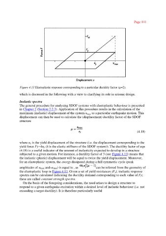
Figure 4.13 Elastoplastic response corresponding to a particular ductility factor (µ=2).
which is discussed in the following with a view to clarifying its role in seismic design.
Inelastic spectra
The general procedure for analysing SDOF systems with elastoplastic behaviour is presented
in Chapter 2 (Section 2.2.3). Application of this procedure results in the calculation of the
maximum (inelastic) displacement of the system u max to a particular earthquake motion. This
displacement can then be used to calculate the (displacement) ductility factor of the SDOF
structure
(4.18)
where uy is the yield displacement of the structure (i.e. the displacement corresponding to the
yield force Fy=kuy (k is the elastic stiffness of the SDOF system)). The ductility factor of eqn
(4.18) is a useful indicator of the amount of inelasticity expected to develop in a structure
subjected to a given motion. For instance, a ductility factor of 3 (see Figure 4.13) means that
the inelastic (plastic) displacement will be equal to twice the yield displacement. Moreover,
for an elastoplastic system, the energy dissipated during a full symmetric cycle (peak
amplitudes of umax and–umax) is equal to , as can be inferred from the geometry of
the elastoplastic loop in Figure 4.13. Given a set of yield resistances (Fy), inelastic response
spectra can be calculated indicating the ductility demand corresponding to each value of Fy;
these are called constant strength spectra.
On the basis of the foregoing considerations, the need arises to design a structure to
respond to a given earthquake excitation within a desired level of inelastic behaviour (i.e. not
exceeding a target ductility). It is therefore particularly useful