Page 119 - Dynamic Vision for Perception and Control of Motion
P. 119

3.4 Behavioral Capabilities for Locomotion    103


                  4                             4
                                       y (m)   3.5         y (m)
                  3                             3
                           ȥ/°                 2.5
                  2  ·                          2
                    ȥ (°/s)
                  1                            1.5                   œ|a y |dt
                                 ȕ/°            1
                  0                            0.5         v y (m/s)  in m/s
                                  Ȝ/°           0
                  -1       ·                  -0.5
                                    ·
                     Control  Ȝ (°/s)  ȥ (°/s)      a y (m/s 2 )
                  -2                           -1
                   0      1      2      3      4      5     6       t /s  8  0          50       100       150         l (m)  250
                                                                    Ȝ = 0
                 (a) Control input time T LC = 6 seconds, no central 0-input arc
                  10  ·                        5
                  8  ȥ/°/s                     4          œ|a y |dt
                  6           ȥ/°      y (m)              in m/s       y/m
                  4                            3
                  2                            2
                  0                                             v y (m/s)
                  -2    ȕ/°    Ȝ/°  · ȥ (°/s)  1
                  -4                           0
                  -6       ·
                  -8  Control Ȝ (°/s)          -1   a y (m/s 2 )
                                               -2
                   0    0.5     1    1.5     2    2.5    3       t /s  4  0        20      40       60      80        l (m) 120
                                                               Ȝ = 0
                  (b) Control input time T LC = 2 seconds, no central 0-input arc
                  10    ·                      5
                  8     ȥ/°                    4         œ|a y |dt
                  6        ȥ/°           y (m)           in (m/s)
                  4                            3
                  2                            2                v y (m/s)
                  0
                  -2                           1
                  -4     ȕ/°  Ȝ/°              0
                  -6       ·     ·
                  -8  Control Ȝ (°/s)  ȥ/ °/s  -1   a y (m/s 2 )
                                               -2
                   0    0.5     1    1.5     2    2.5    3       t /s  4  0        20      40       60      80        l (m) 120
                                                               Ȝ = 0
                  (c) Control input time T LC = 2 seconds like (b), but 0.4 seconds (20 %) central 0-input arc;
                  note that maneuver time is almost 2·T LC = 4 seconds
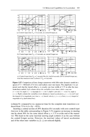
             Figure 3.27. Comparison of lane change maneuvers with fifth-order dynamic model at a
             speed of V = 100 km/h (27.8 m/s) and realistic steer rate inputs. The amplitude A is ad-
             justed such that the lateral offset y f  is exactly one lane width of 3.75 m after the tran-
             sients have settled. Left column shows the variables (over time): dȜ/dt = steer rate
             (        ) in (°/s); angle Ȝ (      ); slip angle ȕ (       ) in (°); dȥ/dt = yaw rate (         ) in (°/s), angle ȥ
             (       ). Right column the variables (over distance): lateral acceleration a y (       ) in (m/s²) and
             the integral of its magnitude over time (       ); lateral velocity v y (       ), offset y (      ); integral of
             magnitude of a y (dash-dotted line).
            (column 8): compared to (a), maneuver time for the complete state transition is re-
            duced from 7.9 to 4.4 s (by ~ 45%).
              Inserting a central section of 20% duration (0.4 seconds) with zero control input
            (last row in the table corresponding to Figure 3.27c requires an increase in steering
            rate by about 30% for the same lateral offset y f = 3.75 m at the end of the maneu-
            ver. This leads to the same maximal steering angle (column 2) as the case without
            the central 0-input section.  However, the  maximal values of lateral acceleration
            and of the other state variables (ȥ, ȕ, v y) are reduced slightly.
   114   115   116   117   118   119   120   121   122   123   124