
Page 186 - Dynamics of Mechanical Systems
P. 186
0593_C06_fm Page 167 Monday, May 6, 2002 2:28 PM
Forces and Force Systems 167
Hence, by substitution into Eq. (6.3.3) we have:
i (
i )
N
O ∑
i ∑
i ∑
M = N p × F = N p + OO × F = ∑ p × F + N OO F i
ˆ
ˆ
×
ˆ
ˆ
i
i
i=1 i=1 i=1 i=1
(6.3.5)
N
= M + OO × ∑ F = M + OO R
ˆ
ˆ
×
O ˆ i O ˆ
i=1
That is,
ˆ
ˆ
×
M = M + OO R and then M = M + OO R (6.3.6)
×
O ˆ O ˆ O
Equation (6.3.6) shows that if we know the resultant R and the moment of S about some
point O we can readily find the moment of S about any other point Ô.
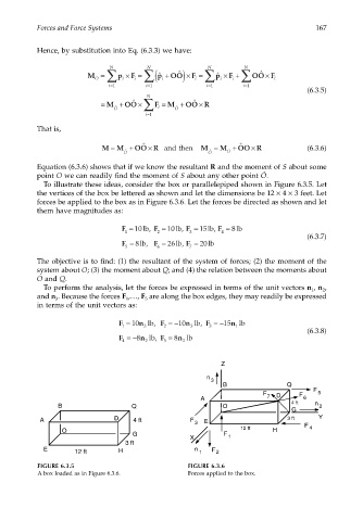
To illustrate these ideas, consider the box or parallelepiped shown in Figure 6.3.5. Let
the vertices of the box be lettered as shown and let the dimensions be 12 × 4 × 3 feet. Let
forces be applied to the box as in Figure 6.3.6. Let the forces be directed as shown and let
them have magnitudes as:
F = 10lb, F = 10lb, F = 15lb, F = lb
8
1 2 3 4
(6.3.7)
8
F = lb, F = 26lb, F = 20lb
5 6 7
The objective is to find: (1) the resultant of the system of forces; (2) the moment of the
system about O; (3) the moment about Q; and (4) the relation between the moments about
O and Q.
To perform the analysis, let the forces be expressed in terms of the unit vectors n , n ,
1
2
and n . Because the forces F ,…, F are along the box edges, they may readily be expressed
3
1
5
in terms of the unit vectors as:
F = 10 n lb, F = − 10 n lb, F = − 15 n lb
1 3 2 3 3 1
(6.3.8)
F =− 8 n lb, F = 8 n lb
4 2 5 2
Z
n
3
B Q
F
F 7 D F 5
A 6
4 ft n
B Q O 2
G
A D 4 ft F 3 ft Y
3 E
12 ft F 4
O H
G F 1
X
3 ft
E 12 ft H n 1 F 2
FIGURE 6.3.5 FIGURE 6.3.6
A box loaded as in Figure 6.3.6. Forces applied to the box.