
Page 110 - Electrical Properties of Materials
P. 110
92 The free electron theory of metals
Electron
collector Ammeter
(a)
A
Metal
A (b)
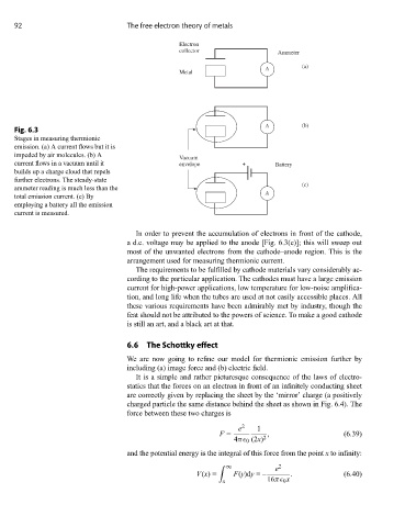
Fig. 6.3
Stages in measuring thermionic
emission. (a) A current flows but it is
impeded by air molecules. (b) A Vacuum
current flows in a vacuum until it envelope + Battery
builds up a charge cloud that repels
further electrons. The steady-state
(c)
ammeter reading is much less than the
A
total emission current. (c) By
employing a battery all the emission
current is measured.
In order to prevent the accumulation of electrons in front of the cathode,
a d.c. voltage may be applied to the anode [Fig. 6.3(c)]; this will sweep out
most of the unwanted electrons from the cathode–anode region. This is the
arrangement used for measuring thermionic current.
The requirements to be fulfilled by cathode materials vary considerably ac-
cording to the particular application. The cathodes must have a large emission
current for high-power applications, low temperature for low-noise amplifica-
tion, and long life when the tubes are used at not easily accessible places. All
these various requirements have been admirably met by industry, though the
feat should not be attributed to the powers of science. To make a good cathode
is still an art, and a black art at that.
6.6 The Schottky effect
We are now going to refine our model for thermionic emission further by
including (a) image force and (b) electric field.
It is a simple and rather picturesque consequence of the laws of electro-
statics that the forces on an electron in front of an infinitely conducting sheet
are correctly given by replacing the sheet by the ‘mirror’ charge (a positively
charged particle the same distance behind the sheet as shown in Fig. 6.4). The
force between these two charges is
e 2 1
F = , (6.39)
4π 0 (2x) 2
and the potential energy is the integral of this force from the point x to infinity:
∞ e
2
V(x)= F(y)dy =– . (6.40)
x 16π 0 x