
Page 114 - Electrical Properties of Materials
P. 114
96 The free electron theory of metals
Fluorescent screen
Fine point
+
4
0 –10 V
Vacuum Power
envelope supply
–
Fig. 6.9
Sketch showing the principle of the
field-emission microscope.
the anode, which creates at the tip an electric field high enough to draw out
electrons. The emitted electrons follow the lines of force and produce a mag-
nified picture (magnification = r 2 /r 1 , where r 2 = radius of the screen and r 1 =
radius of the tip) on the fluorescent screen. Since the magnification may be as
6
large as 10 , we could expect to see a periodic variation in the electron emis-
sion caused by the atomic structure. The failure to observe this is explained by
two reasons: quantum-mechanical diffraction, and deviation from the ‘theoret-
ical’ course owing to a random transverse component in the electron velocity
when leaving the metal.
The limitations we have just mentioned can be overcome by introducing
helium into the chamber and reversing the polarity of the applied potential.
The helium atoms that happen to be in the immediate vicinity of the tungsten
tip become ionized owing to the large electric field, thus acquiring a posit-
ive charge, and move to the screen. Both the quantum-mechanical diffraction
(remember, the de Broglie wavelength is inversely proportional to mass) and
the random thermal velocities are now smaller, so that the resolution is higher
and individual atoms can indeed be distinguished as shown in Fig. 6.10. This
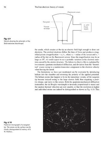
Fig. 6.10
Field-ion micrograph of a tungsten
tip. The atoms on the surface can be
clearly distinguished (Courtesy of E.
W. Muller).