Page 145 - Electromechanical Devices and Components Illustrated Sourcebook
P. 145

Chapter 6  Rotating Components 107


                            M                                                        M

                                                                                Schematic Symbol
                      Schematic Symbol
                                                                     Field Terminals
          Terminals             Frame                             Armature                  Frame
                                                                  Terminals


                                                                 Brushes                                 Output
                                                                                                         Shaft
         Brushes                                Output Shaft
                                                                 Shunt Coil
                                                                 Screws
          Magnet
                                                                                                   Mount
          Screws
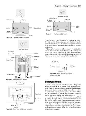
                                                                 Figure 6-6 Shunt Wound DC Motor
                                         Mount
         Figure 6-3 Permanent Magnet DC Motor
                                                              Figure 6-6 shows a typical commercial shunt wound motor.
                                                              Note that most of these motors also have facilities to easily
                               M                              replace the brush set. Like the permanent magnet motor, this
                                                              is the part of a shunt wound motor that most often requires
                                                              maintenance.
                                                                 The speed of a shunt wound motor can be controlled by
                          Schematic Symbol
                                                              limiting the current that the field receives. By lowering the
            Rotor Core
                                                              current, field strength lowers and the motor produces a lower
             Rotor Coil                        Armature       speed. Figure 6-7 shows a schematic representation of how a
                                                              shunt wound motor can be configured for speed control.
                                                Rotor Pole
                 Axle
          Magnet Pole                          Brush
                                                                        Field Winding


                                                Shunt                 Armature  M                DC Power
                                                Winding

                                                                                 Rheostat
                                                                      Figure 6-7 Shunt Wound Motor Speed
           Brush Spring
                                                                      Control Schematic
                                                 Terminal
          Figure 6-4 Shunt Wound DC Motor
                                                              Universal Motors
                       Shunt Winding
                                                              A universal motor is a shunt wound motor that is designed to
                                                              operate on either AC or DC power. These motors are com-
                                                              monly found on sewing machines as they provide excellent
                     Electromagnet Core
                                                              speed control at a low cost per unit. Figure 6-8 shows a typical
                       Axle
                                                              universal motor. The appearance of a universal motor differs
                                                              very little from most DC motors and usually the difference
                                                 Rotor Core
                                                              can’t be determined without reading the nameplate.
                                                                 Controlling the speed of a universal motor is accomplished
                                                 Rotor Coil   by varying the input voltage. Variable autotransformers are
                                                              ideal for this service. Figure 6-9 shows a schematic of a uni-
                                                              versal motor speed control utilizing a variable autotrans-
                                        Terminals             former. Figure 6-10 shows a high/medium/low speed control
                Armature                                      using a multi-tap transformer. Figure 6-11 shows speed control
                    Brushes                                   accomplished using an electronic SCR (silicone-controlled
         Figure 6-5 Shunt Wound DC Motor Schematic            rectifier) speed controller.
   140   141   142   143   144   145   146   147   148   149   150