
Page 148 - Electromechanical Devices and Components Illustrated Sourcebook
P. 148
110 Electromechanical Devices & Components Illustrated Sourcebook
motors are supplied on what is termed a resilient mount. Start Capacitor Centrifugal Switch
These mounts are specifically designed to minimize noise
and vibration.
Run Capacitor
Split Capacitor Motors
AC Power
Split capacitor motors are similar in design to a capacitor start Rotor
motor, except that the centrifugal switch is eliminated from Run Winding
the assembly. The start winding is connected to the power
source through a capacitor and is designed to be continuously
energized. This sets up a continuous asymmetry in the field
Start Winding
and, therefore, the power of the start winding must be mini-
mal. Figure 6-19 shows a schematic of a split phase motor. Figure 6-21 Capacitor Start/Capacitor Run Motor
These motors have poor starting torque and generally provide Schematic
poor efficiency. They are usually used in low fractional horse-
power applications. One real advantage of these motors is that
they have very few moving parts and are extremely reliable.
They are excellent choices for small equipment for which reg- through a centrifugal switch. During start-up, the start capacitor
ular maintenance is difficult or impossible. Figure 6-20 shows creates a gross asymmetry in the fields and very high start
a typical split capacitor motor. torques are generated. As the motor speed increases, the cen-
trifugal switch opens and the run capacitor creates a moderate
asymmetry in the field. Figure 6-21 shows a capacitor
start/capacitor run motor schematic. This arrangement is typ-
Capacitor
ically configured to produce high horsepower from relatively
small packages. These motors also exhibit excellent efficien-
cies. They represent a very good choice for small equipment
AC Power that requires high starting torques, such as compressors,
Rotor machine tools, and conveyor systems. Figure 6-22 shows a
commercial capacitor start/capacitor run motor. The telltale of
Run Winding
these motors are the two cylindrical capacitor housing that are
normally mounted on the top of the frame.
Start Winding
Figure 6-19 Split Capacitor Motor Schematic
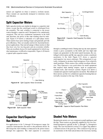
Start Capacitor
Run Capacitor
Capacitor Frame End Plate Frame Cover
Wires Frame Bolts End Plates Conduit
Insulating Connection
Boot Frame Bolts Leads Box
Capacitor Output Name Plate
220 VAC Shaft Key Seat
Mount
Output Shaft
Cooling Mount Bearing Seal
Shroud Cooling Vents
AC Power
Figure 6-22 Capacitor Start/Capacitor Run Motor
Figure 6-20 Split Capacitor Motor
Capacitor Start/Capacitor Shaded Pole Motors
Run Motors Shaded pole motors are very common in small appliances and
the like. These motors are generally supplied in very low frac-
1
3
1
For applications in the / through 10 horsepower range, the tional horsepower, typically in the / through / 120 horsepower
4
16
capacitor start/capacitor run motor is the preferred choice. In range. The start mechanism consists of a copper ring added to
this design the start winding is connected to the power source a limited section of the pole face. This conductor loop sets up
through two capacitors. The start capacitor is connected an asymmetry in the field and produces the necessary starting