Page 152 - Electromechanical Devices and Components Illustrated Sourcebook
P. 152

114 Electromechanical Devices & Components Illustrated Sourcebook

                                                                                                 Speed (Oscillator)
                                                                                                 Speed (0 to 10 Volts)
                                                                                                 Run
                          3                                                                      Single Step
                       2     4
                                                                                                 CW/CCW
                     1         5          Between Poles
                        Rotor
                    6
                                 6
                                                                                           Stepper
                     5          1                                                          Controller
                       4     2
                          3
                                                                  Stepper
                                                                   Motor                                 120 VAC
              Figure 6-33 Half-Step Position
                                                                                  Pole
                                                                                 Switches
                                                                                            DC Power
                                                                                             Supply
                                                               Figure 6-36 Stepper Motor Control


                          3
                       2     4
                     1         5         Multi Positional     Servo Motors
                            Rotor
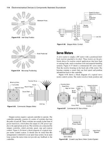
                  6               6                           A servo motor is simply a DC motor with a positional feed-
                                                              back resolver attached to its shaft. These motors are the pre-
                     5         1
                                                              ferred choice for motion control applications that have high
                       4     2
                          3
                                                              or varying loads, such as machine tools and material-handling
                                                              systems. Figure 6-37 shows a commercial DC servo motor.
                                                              Note the resolver housing on the back side of the motor. The
             Figure 6-34  Microstep Positioning               housing contains a sensor that can feed speed and position
                                                              information back to the controller.
                                                                 Figure 6-38 shows a block diagram of a typical servo
                                                              motor control system. The motor resolver feeds position and

                                Terminal Wires
            Mounting Holes
                                                                   Mounting Holes
              Frame Bolts           Frame                                                       Speed & Position
                                                                    Frame Bolts     Leads Box
                            Mount Flange                                                          Data Port
                 Alignment Boss
                                                                        Alignment Boss  Cooling    Resolver
                                                                                    Fins
                                                                               Mount               Housing
                         Output Shaft
                                                                               Flange


                                            End Cap
                                                                              Output Shaft
         Figure 6-35 Commercial Stepper Motor                                                 Brushes
                                                               Figure 6-37 Commercial DC Servo Motor


           Stepper motors require a special controller to operate. The
        controller generally consists of a series of switches that turn
        the poles on and off. These switches are usually in the form of
                                                                                Variable DC
        power transistors, which direct the output of a DC power sup-          Power Supply
        ply to the appropriate pole set. The switches are connected the
        stepper controller, which provides speed, step and rotation
        control. Figure 6-36 shows a block diagram of a typical step-                                 Input From
        per motor control system. It should also be noted that this                                    System
        arrangement is referred to as an open-loop system. In an open                     Controller
        loop system the motor does not provide any feedback to the    Servo Motor
        controller.                                              Figure 6-38 Closed-Loop Servo Motor Control System
   147   148   149   150   151   152   153   154   155   156   157