Page 155 - Electromechanical Devices and Components Illustrated Sourcebook
P. 155

Chapter 6  Rotating Components 117

                                                              Variable Frequency Drives
                                 Actuator Arm
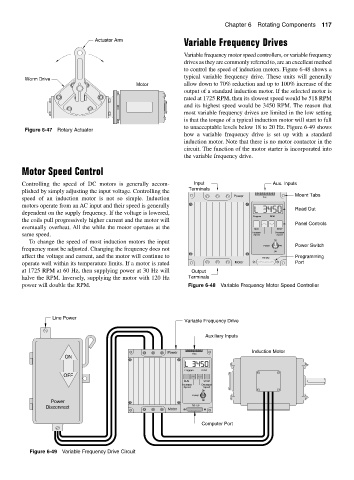
                                                              Variable frequency motor speed controllers, or variable frequency
                                                              drives as they are commonly referred to, are an excellent method
                                                              to control the speed of induction motors. Figure 6-48 shows a
                                                              typical variable frequency drive. These units will generally
         Worm Drive
                                              Motor           allow down to 70% reduction and up to 100% increase of the
                                                              output of a standard induction motor. If the selected motor is
                                                              rated at 1725 RPM, then its slowest speed would be 518 RPM
                                                              and its highest speed would be 3450 RPM. The reason that
                                                              most variable frequency drives are limited in the low setting
                                                              is that the torque of a typical induction motor will start to fall
                                                              to unacceptable levels below 18 to 20 Hz. Figure 6-49 shows
         Figure 6-47 Rotary Actuator
                                                              how a variable frequency drive is set up with a standard
                                                              induction motor. Note that there is no motor contactor in the
                                                              circuit. The function of the motor starter is incorporated into
                                                              the variable frequency drive.

        Motor Speed Control

        Controlling the speed of DC motors is generally accom-    Input                     Aux. Inputs
        plished by simply adjusting the input voltage. Controlling the  Terminals                  Mount Tabs
        speed of an induction motor is not so simple. Induction                Power     Aux.
        motors operate from an AC input and their speed is generally
                                                                                                   Read Out
        dependent on the supply frequency. If the voltage is lowered,
                                                                                     Program  RPM
        the coils pull progressively higher current and the motor will
                                                                                                   Panel Controls
        eventually overheat. All the while the motor operates at the                  RUN    STOP
        same speed.                                                                  Increase  Decrease
                                                                                             Speed
                                                                                     Speed
           To change the speed of most induction motors the input                           On
                                                                                         Power     Power Switch
        frequency must be adjusted. Changing the frequency does not
                                                                                            Off
        affect the voltage and current, and the motor will continue to                  RS-232     Programming
        operate well within its temperature limits. If a motor is rated        Motor               Port
        at 1725 RPM at 60 Hz, then supplying power at 30 Hz will  Output
        halve the RPM. Inversely, supplying the motor with 120 Hz  Terminals
        power will double the RPM.                              Figure 6-48 Variable Frequency Motor Speed Controller


                   Line Power
                                                              Variable Frequency Drive

                                                                     Auxiliary Inputs

                                                         Power   Aux.                Induction Motor
                       ON

                                                              Program  RPM
                      OFF
                                                              RUN    STOP
                                                              Increase  Decrease
                                                              Speed  Speed
                                                                    On
                                                                 Power
                  Power                                             Off
                Disconnect                               Motor   RS-232

                                                                    Computer Port


           Figure 6-49 Variable Frequency Drive Circuit
   150   151   152   153   154   155   156   157   158   159   160