
Page 156 - Electromechanical Devices and Components Illustrated Sourcebook
P. 156
118 Electromechanical Devices & Components Illustrated Sourcebook
Another function that variable frequency drives can pro- Delay Time
vide is soft starting. Soft starting is useful for applications that Zero Crossing On Time
have high inertial loads, such as heavy flywheels and cable
spools. If a motor is exposed to an excessively long start cycle
it may overheat and can be severely damaged. By starting a
motor at a lower RPM, the starting load may be mitigated. Start Ramp Up Run
Figure 6-50 shows the progression of a variable frequency Figure 6-52 Soft Starter Switching Cycle
drive during a soft start cycle.
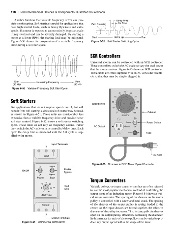
SCR Controllers
Universal motors can be controlled with an SCR controller.
These controllers switch the AC cycle to vary the total power
that the motor receives. Figure 6-53 shows an SCR controller.
These units are often supplied with an AC cord and recepta-
cle so that they may be simply plugged in.
Start Increasing Frequency Run
(30 Hz) (60 Hz)
Figure 6-50 Variable Frequency Soft Start Cycle
50
40 60
30 70
Soft Starters 20 80
Speed Knob
For applications that do not require speed control, but will 10 90
benefit from soft starting, a dedicated soft starter may be used,
0 100 Cabinet
as shown in Figure 6-51. These units are considerably less Speed %
expensive than a variable frequency drive and provide better On
soft start control. Figure 6-52 shows a soft starter switching Power Power Switch
cycle. These units do not rely on frequency control, rather
AC Output Output Off
they switch the AC cycle on at a controlled delay time. Each
cycle the delay time is shortened until the full cycle is sup- Fuse Fuse
plied to the motor.
Input Terminals
AC Cord
Input
Figure 6-53 Commercial SCR Motor Speed Controller
On Enable
Enable
On/Off
Bypass
Off Bypass
Power Start
Torque Converters
15
10 20
Start Variable pulleys, or torque converters as they are often referred
5 25 Time
0 30 to, are the most popular mechanical method of controlling the
output speed of an induction motor. Figure 6-54 shows a typi-
Start Time
cal torque converter. The spacing of the sheaves on the motor
pulley is controlled with a screw and hand crank. The spacing
Output of the sheaves of the output pulley is spring loaded to the
center. As the input sheaves are forced together, the effective
diameter of the pulley increases. This, in turn, pulls the sheaves
apart on the output pulley, effectively decreasing the diameter.
Output Terminals In this manner the ratio of the two pulleys can be varied to pro-
Figure 6-51 Commercial Soft Starter duce any output speed within the range of the drive.