
Page 153 - Electromechanical Devices and Components Illustrated Sourcebook
P. 153
Chapter 6 Rotating Components 115
speed information back to the controller. The controller uses Speed Reduction
this information to adjust the output of the power supply,
assuring the motor operates within the parameters that the Motor speed reduction is necessary for a variety of applica-
system requires. This type of system is referred to as a closed- tions. There are three basic power transmission systems in
loop system. common use today—gear, belt, and chain. However, there are
a myriad of variations within each of these categories, which
makes power transmission a broad topic that is too extensive
Solenoid/Piston Motors for the scope of this book.
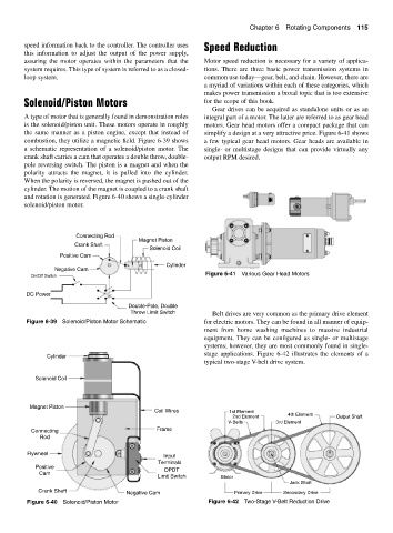
Gear drives can be acquired as standalone units or as an
A type of motor that is generally found in demonstration roles integral part of a motor. The latter are referred to as gear head
is the solenoid/piston unit. These motors operate in roughly motors. Gear head motors offer a compact package that can
the same manner as a piston engine, except that instead of simplify a design at a very attractive price. Figure 6-41 shows
combustion, they utilize a magnetic field. Figure 6-39 shows a few typical gear head motors. Gear heads are available in
a schematic representation of a solenoid/piston motor. The single- or multistage designs that can provide virtually any
crank shaft carries a cam that operates a double throw, double- output RPM desired.
pole reversing switch. The piston is a magnet and when the
polarity attracts the magnet, it is pulled into the cylinder.
When the polarity is reversed, the magnet is pushed out of the
cylinder. The motion of the magnet is coupled to a crank shaft
and rotation is generated. Figure 6-40 shows a single-cylinder
solenoid/piston motor.
Connecting Rod
Magnet Piston
Crank Shaft
Solenoid Coil
Positive Cam
S N Cylinder
Negative Cam
Figure 6-41 Various Gear Head Motors
On/Off Switch
DC Power
Double-Pole, Double
Throw Limit Switch Belt drives are very common as the primary drive element
Figure 6-39 Solenoid/Piston Motor Schematic for electric motors. They can be found in all manner of equip-
ment from home washing machines to massive industrial
equipment. They can be configured as single- or multistage
systems; however, they are most commonly found in single-
stage applications. Figure 6-42 illustrates the elements of a
Cylinder
typical two-stage V-belt drive system.
Solenoid Coil
Magnet Piston
Coil Wires 1st Element
2nd Element 4th Element Output Shaft
V-Belts 3rd Element
Connecting Frame
Rod
Flywheel
Input
Terminals
Positive DPDT
Cam
Limit Switch Motor
Jack Shaft
Crank Shaft Negative Cam Primary Drive Secondary Drive
Figure 6-40 Solenoid/Piston Motor Figure 6-42 Two-Stage V-Belt Reduction Drive