
Page 151 - Electromechanical Devices and Components Illustrated Sourcebook
P. 151
Chapter 6 Rotating Components 113
• Type-Motor type, that is capacitor start, reversing, high Stepper Motors
temperature, TEFC, compressor rated, wound rotor, and
so on. Stepper motors are generally used for motion control applica-
• H.P.-Full load horsepower. tions. These motors are excellent for equipment that has low
or fairly consistent loads. The stepper motor is a multipole
• Amps-Full load current (not starting current).
design that allows extremely precise positioning of the rotor,
If the motor is a dual-voltage unit the first number
even at 0 RPM. This attribute make them very friendly to the
is for low voltage and the second is for high
motion control engineer and these motors are found in most
voltage.
computer equipment such as disk drives and printers.
• RPM-Full load revolutions per minute. If the
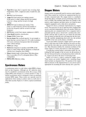
Figure 6-32 shows a schematic representation of a stepper
motor is a dual-frequency unit the first number is
motor. The motor has six sets of opposing stator windings that
for the low frequency and the second is for high
can be controlled independently from one another. When two
frequency.
opposing poles are energized (poles five) a magnetic field is
• DUTY-Duty cycle (Cont. means continuous or 100%)
generated and the rotor is forced into a position that corre-
• Class Insul-Insulation classification. sponds with the field. If poles five are turned off and poles
• Frame-NEMA Frame type. four are turned on then the rotor will jump into the new posi-
• Service factor-The overload capacity. As an example, a tion. By carefully manipulating these pole sets, the position
motor that has a service factor of 1.25 is able to produce and RPM of the rotor can be closely controlled.
25% more continuous horsepower then the nameplate To provide further resolution, stepper motors can be oper-
states without damage. ated in a half-step mode. In this operation four poles are ener-
gized and the rotor takes up a position between the two pole
• Volts-Line voltage.
sets. This effectively doubles the rotational resolution of the
• Hertz-Line frequency to produce rated RPM. If the
motor. Figure 6-33 shows the motor in a half-step position.
motor is a dual-voltage unit the frequency is displayed
Carrying this concept further is microstep control. By con-
with the lower frequency first (50/60)
trolling the field strength of the two pole sets the position of
• Phase-Labeled single or three phase. With three phase
the rotor between the poles can be placed anywhere within the
there is generally a D or Y to designate Delta or Wye
arc. Figure 6-34 shows the motor in microstep mode.
configuration.
Figure 6-35 shows a typical commercial stepper motor.
• NEMA Eff.-Efficiency rating. These motors are usually supplied with a mounting flange
which includes an alignment boss. The position of the output
shaft in reference to the alignment boss is very precise and is
Synchronous Motors appropriate for mounting the motor directly into a gear box.
A synchronous motor is a unit whose output RPM is depen-
dent on line frequency. Although any AC induction motor
may be considered a synchronous motor, the accuracy of the
output RPM varies because of a certain amount of “slip.” A
typical synchronous motor is designed to have an extremely
accurate RPM output. These motors are typically used for
applications where timing is critical, such as a wall clock or Pole Coil
3
strip chart recorder. Figure 6-31 shows a typical synchronous 2 4
motor. 1 5
Rotor
6 6 Pole Core
5 1
4 2
3
Terminal Wires
Mount Flange Output Shaft
Pole 1
Pole 2
Pole 3 To Controller
Pole 4
Pole 5
Frame Pole 6
Figure 6-31 Synchronous Motor Figure 6-32 Six-Pole Stepper Motor Schematic