
Page 147 - Electromechanical Devices and Components Illustrated Sourcebook
P. 147
Chapter 6 Rotating Components 109
Bearing Conductors Capacitor Housing
Frame
Shaft End Ring Nameplate
End Plate Rotor
Frame
Bolts
Output
Laminations Shaft
End Ring
Conductors
Figure 6-14 Squirrel Cage Rotor
Mount
AC Cord
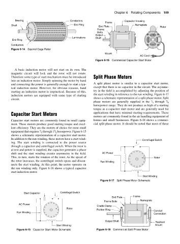
Figure 6-16 Commercial Capacitor Start Motor
A basic induction motor will not start on its own. The
magnetic circuit will lock and the rotor will not rotate.
Therefore some type of start mechanism must be introduced Split Phase Motors
into an induction motor. Simply spinning the motor by hand
A split phase motor is similar to a capacitor start motor,
and connecting the power is generally enough to start a typ-
except that there is no capacitor in the circuit. The asymme-
ical induction motor. However, for obvious reasons, hand
try in the field is accomplished by adjusting the position of
starting an induction motor is impractical. Because of this,
the start winding in reference to the run winding. Figure 6-17
induction motors are equipped with some type of starting
shows a schematic representation of a split phase motor. Split
circuit.
1 3
phase motors are generally supplied in the / 4 through / 4
horsepower range. They do not produce as high of a starting
torque as a capacitor start motor and are generally used for
Capacitor Start Motors applications that have minimal starting requirements. These
motors are commonly found in the air handling equipment of
Capacitor start motors are commonly found in small equip- homes and small businesses. Figure 6-18 shows a commer-
ment. These motors produce good starting torque and excel- cial split phase motor. It should be noted that most of these
lent efficiency. They are the motors of choice for most small
1
1
equipment that requires / through 1 / horsepower. Figure 6-15
2
2
shows a schematic representation of a capacitor start motor.
In addition to the run winding, these motors have a start wind- Centrifugal Switch
ing. The start winding is connected to the power source
through a capacitor and centrifugal switch. When the rotor is
at rest and power is supplied, the capacitor generates a phase
shift and the start winding creates asymmetry in the field. AC Power
This, in turn, starts the rotation of the rotor. As the speed of Rotor
the rotor increases, the centrifugal switch opens and discon- Run Winding
nects the start winding. At this point, the motor operates on
the run winding only. Figure 6-16 shows a typical capacitor
start induction motor.
Start Winding
Figure 6-17 Split Phase Motor Schematic
Start Capacitor Centrifugal Switch
End Plate Frame
Nameplate
Frame Bolts
AC Power
Cradle Clamp
Rotor
Rubber Ring Conduit
Run Winding
Connection
Output Shaft Resilient
Start Winding Mount
Figure 6-15 Capacitor Start Motor Schematic Figure 6-18 Commercial Split Phase Motor