
Page 150 - Electromechanical Devices and Components Illustrated Sourcebook
P. 150
112 Electromechanical Devices & Components Illustrated Sourcebook
800 300
700
250
600
Current
500
200
400 % of Full Load Torque
300
150
200
% of Full Load Current
Torque
100 100
0 0
0 10 20 30 40 50 60 70 80 90 100
Motor Speed (%)
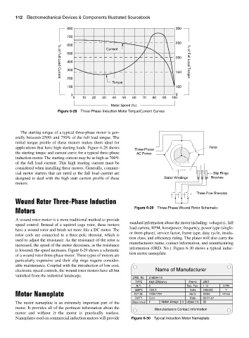
Figure 6-28 Three-Phase Induction Motor Torque/Current Curves
The starting torque of a typical three-phase motor is gen-
erally between 250% and 750% of the full load torque. The
initial torque profile of these motors makes them ideal for
applications that have high starting loads. Figure 6-28 shows Rotor
Three-Phase
the starting torque and current curve for a typical three-phase AC Power
induction motor. The starting current may be as high as 700%
of the full load current. This high starting current must be
considered when installing these motors. Generally, commer-
cial motor starters that are rated at the full load current are Slip Rings
designed to deal with the high start current profile of these Stator Windings Brushes
motors.
Three Pole Rheostat
Wound Rotor Three-Phase Induction
Motors Figure 6-29 Three-Phase Wound Rotor Schematic
A wound rotor motor is a more traditional method to provide
standard information about the motor including: voltage(s), full
speed control. Instead of a squirrel cage rotor, these motors
load current, RPM, horsepower, frequency, power type (single-
have a wound rotor and brush set more like a DC motor. The
or three-phase), service factor, frame type, duty cycle, insula-
rotor coils are connected to a three-pole rheostat, which is
tion class, and efficiency rating. The plates will also carry the
used to adjust the resistance. As the resistance of the rotor is
manufacturers name, contact information, and manufacturing
increased, the speed of the motor decreases, as the resistance
information (ORD. No.). Figure 6-30 shows a typical induc-
is lowered, the speed increases. Figure 6-29 shows a schematic
tion motor nameplate.
of a wound rotor three-phase motor. These types of motors are
particularly expensive and their slip rings require consider-
able maintenance. Coupled with the introduction of low cost,
electronic speed controls, the wound rotor motors have all but Name of Manufacturer
vanished from the industrial landscape.
ORD. No. 216B347-H
TYPE High Efficiency Frame 286T
H.P. 5 Sev. Fac. 1.10 3 PH
AMPS 13/6.5 Volts 240/480 Y
Motor Nameplate R.P.M. 1430/1724 Hertz 50/60 4 Pole
DUTY Cont. Date 03-11-57
The motor nameplate is an extremely important part of the Class Insul F NEMA Design B NEMA Eff. 95
motor. It provides all of the pertinent information about the Manufacturers Contact Information
motor and without it the motor is practically useless.
Nameplates used on commercial induction motors will provide Figure 6-30 Typical Induction Motor Nameplate