
Page 146 - Electromechanical Devices and Components Illustrated Sourcebook
P. 146
108 Electromechanical Devices & Components Illustrated Sourcebook
Induction Motors
M
By far, the largest class of electric motors are induction
motors. These motors represent the most efficient use AC
Schematic Symbol power and are the least expensive class of motor to manufac-
ture. They can be designed to produce outputs from low frac-
Frame
tional horsepower to tens of thousands of horsepower.
Terminal Induction motors are found in virtually every home, office,
Wires Cooling Vents
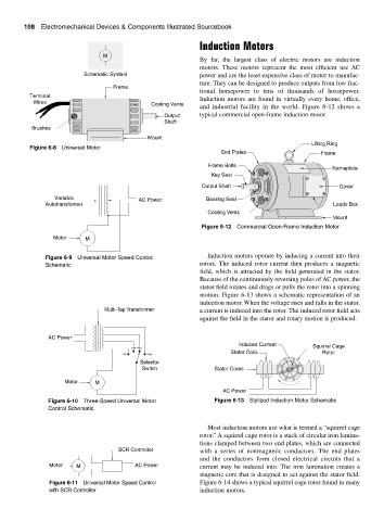
and industrial facility in the world. Figure 6-12 shows a
Output typical commercial open-frame induction motor.
Shaft
Brushes
Mount
Lifting Ring
Figure 6-8 Universal Motor
End Plates Frame
Frame Bolts
Nameplate
Key Seat
Output Shaft Cover
Variable AC Power Bearing Seal
Autotransformer Leads Box
Cooling Vents
Mount
Figure 6-12 Commercial Open-Frame Induction Motor
Motor M
Induction motors operate by inducing a current into their
Figure 6-9 Universal Motor Speed Control
Schematic rotors. The induced rotor current then produces a magnetic
field, which is attracted by the field generated in the stator.
Because of the continuously reversing poles of AC power, the
stator field rotates and drags or pulls the rotor into a spinning
motion. Figure 6-13 shows a schematic representation of an
induction motor. When the voltage rises and falls in the stator,
Multi-Tap Transformer a current is induced into the rotor. The induced rotor field acts
against the field in the stator and rotary motion is produced.
AC Power
Induced Current Squirrel Cage
Low Med
Stator Coils Rotor
Off High
Selector
Switch Stator Cores
Motor M
AC Power
Figure 6-10 Three-Speed Universal Motor Figure 6-13 Stylized Induction Motor Schematic
Control Schematic
Most induction motors use what is termed a “squirrel cage
rotor.” A squirrel cage rotor is a stack of circular iron lamina-
tions clamped between two end plates, which are connected
SCR Controller with a series of nonmagnetic conductors. The end plates
and the conductors form closed electrical circuits that a
Motor M AC Power current may be induced into. The iron lamination creates a
magnetic core that is designed to act against the stator field.
Figure 6-11 Universal Motor Speed Control Figure 6-14 shows a typical squirrel cage rotor found in many
with SCR Controller induction motors.