
Page 157 - Electromechanical Devices and Components Illustrated Sourcebook
P. 157
Chapter 6 Rotating Components 119
Output Pulley
Preload Springs
Output Shaft Floating Sheaves Output Shaft
Thrust Bearing
Motor Adjustment Screw
Crank
Moving
Sheave
Frame
Belt
Fixed Sheave
High Output Speed Low Output Speed
Figure 6-54 Torque Converter
Generators
G
As we reviewed in Chapter 1, moving a coil of wire through a
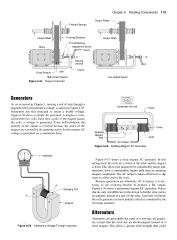
magnetic field will generate a voltage, as shown in Figure 6-55. Schematic Symbol Frame
Generators use this principal to create a usable voltage.
Figure 6-56 shows a simple AC generator. A magnet is rotat-
ed between two coils. Each time a pole of the magnet passes
the coils, a voltage in generated. Every half-revolution the
polarity of the output is reversed because the poles of the
N S Cores
magnet are reversed by the spinning action. In this manner AC
voltage is generated on a continuous basis. Rotating
Magnet
Axle Coils
AC Output
Figure 6-56 Rotating Magnet AC Generator
+/− Voltmeter
− +
Figure 6-57 shows a fixed magnet AC generator. In this
arrangement the coils are carried on the rotor and the magnet
is fixed. This allows the magnet to be considerably larger and,
therefore, have a considerably higher field than its spinning
magnet counterpart. The AC output is taken off from two slip
rings on either end of the rotor.
Because generators are inherently AC in nature, it is nec-
essary to use reversing brushes to produce a DC output.
Figure 6-58 shows a permanent magnet DC generator. Notice
Swinging Coil
that the only real difference in the design is that the rotor carries
N
an armature instead of a pair of slip rings. Each half-revolution
the coils generate a reverse polarity, which is countered by the
S Magnet reversing armature.
Alternators
Alternators are principally the same as a moving coil genera-
tor, except that the rotor has an electromagnet instead of a
Figure 6-55 Generating Voltage Through Induction fixed magnet. This allows a greater field strength than could