
Page 158 - Electromechanical Devices and Components Illustrated Sourcebook
P. 158
120 Electromechanical Devices & Components Illustrated Sourcebook
Rotating Coils
Slip Rings
Axle Rotating Core
G
Pole Coil
Schematic Symbol
Pole Core
Field
Power Supply
Permanent Output
Magnet
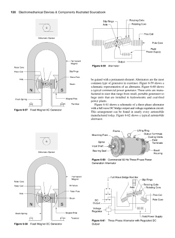
Figure 6-59 Alternator
Rotor Core
Rotor Coil Slip Rings
Rotor Pole
Axle be gained with a permanent element. Alternators are the most
common type of generator in existence. Figure 6-59 shows a
Brush
schematic representation of an alternator. Figure 6-60 shows
N S a typical commercial power generator. These units are manu-
factured in sizes that range from small, portable generators to
huge units that are installed in hydroelectric and coal-fired
Brush Spring Magnet Pole
power plants.
Terminal Figure 6-61 shows a schematic of a three-phase alternator
with a full wave DC bridge output and voltage regulation circuit.
Figure 6-57 Fixed Magnet AC Generator
This arrangement can be found in nearly every automobile
manufactured today. Figure 6-62 shows a typical automobile
alternator.
Frame Lifting Ring
Output Terminals
Mounting Plate
Cooling Vents
Field
G Spline Terminals
Input Shaft
Bearing Seal Brush
Schematic Symbol
Housing
Figure 6-60 Commercial 60 Hz Three-Phase Power
Generation Alternator
Permanent Full Wave Bridge Rectifier
Magnet Slip Rings
Rotor Core
Rotating Coils
Rotor Coil Armature
Axle Rotating Core
Rotor Pole
Axle
Pole Coil
Brush −
DC Pole Core
N S Output +
Voltage
Regulator
Brush Spring Magnet Pole
Field Power Supply
Terminal
Figure 6-61 Three-Phase Alternator with Regulated DC
Figure 6-58 Fixed Magnet DC Generator Output