Page 161 - Electromechanical Devices and Components Illustrated Sourcebook
P. 161

Chapter 6  Rotating Components 123

                                                              The unit may use a 24-VDC input and produce a 600 VAC,
                                                              400 Hz output that is specified for a special piece of equip-
                            G        M                        ment. Dynamotors have been almost completely replaced by
                                                              solid state power supplies.

                          Schematic Symbol
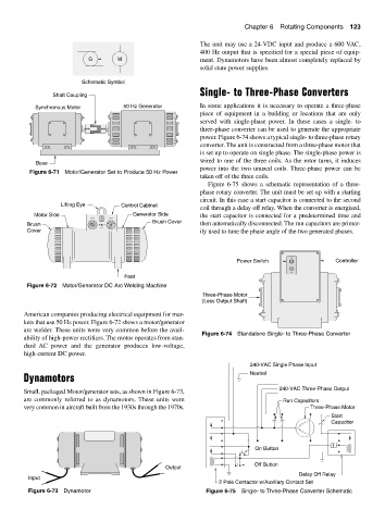
                                                              Single- to Three-Phase Converters
                 Shaft Coupling
            Synchronous Motor          50 Hz Generator        In some applications it is necessary to operate a three-phase
                                                              piece of equipment in a building or locations that are only
                                                              served with single-phase power. In these cases a single- to
                                                              three-phase converter can be used to generate the appropriate
                                                              power. Figure 6-74 shows a typical single- to three-phase rotary
                                                              converter. The unit is constructed from a three-phase motor that
                                                              is set up to operate on single phase. The single-phase power is
                                                              wired to one of the three coils. As the rotor turns, it induces
            Base
                                                              power into the two unused coils. Three-phase power can be
          Figure 6-71 Motor/Generator Set to Produce 50 Hz Power
                                                              taken off of the three coils.
                                                                 Figure 6-75 shows a schematic representation of a three-
                                                              phase rotary converter. The unit must be set up with a starting
                                                              circuit. In this case a start capacitor is connected to the second
                    Lifting Eye       Control Cabinet
                                                              coil through a delay off relay. When the converter is energized,
           Motor Side                     Generator Side      the start capacitor is connected for a predetermined time and
                                                Brush Cover
         Brush                                                then automatically disconnected. The run capacitors are primar-
         Cover                                                ily used to tune the phase angle of the two generated phases.


                                                                          Power Switch                  Controller
                                       Feet
         Figure 6-72 Motor/Generator DC Arc Welding Machine
                                                               Three-Phase Motor
                                                               (Less Output Shaft)

        American companies producing electrical equipment for mar-
        kets that use 50 Hz power. Figure 6-72 shows a motor/generator
        arc welder. These units were very common before the avail-
                                                               Figure 6-74 Standalone Single- to Three-Phase Converter
        ability of high-power rectifiers. The motor operates from stan-
        dard  AC power and the generator produces low-voltage,
        high-current DC power.
                                                                              240-VAC Single Phase Input
                                                                             Neutral
        Dynamotors
                                                                                       240-VAC Three-Phase Output
        Small, packaged Motor/generator sets, as shown in Figure 6-73,
        are commonly referred to as dynamotors. These units were                        Run Capacitors
        very common in aircraft built from the 1930s through the 1970s.                         Three-Phase Motor
                                                                                                      Start
                                                                                                      Capacitor


                                                                                                       T
                                                                               On Button
                                                                               Off Button
                                                    Output
                                                                                             Delay Off Relay
          Input
                                                                    2 Pole Contactor w/Auxiliary Contact Set
          Figure 6-73 Dynamotor                                 Figure 6-75 Single- to Three-Phase Converter Schematic
   156   157   158   159   160   161   162   163   164   165   166