
Page 160 - Electromechanical Devices and Components Illustrated Sourcebook
P. 160
122 Electromechanical Devices & Components Illustrated Sourcebook
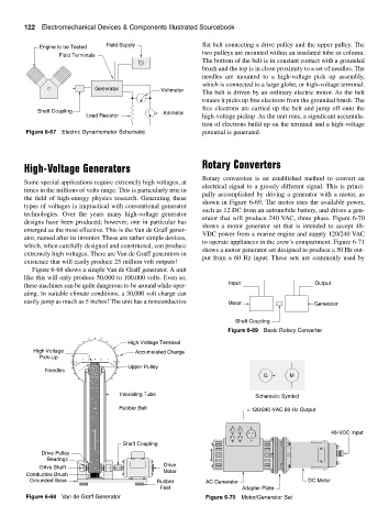
Field Supply flat belt connecting a drive pulley and the upper pulley. The
Engine to be Tested
two pulleys are mounted within an insulated tube or column.
Field Terminals
The bottom of the belt is in constant contact with a grounded
brush and the top is in close proximity to a set of needles. The
needles are mounted to a high-voltage pick up assembly,
which is connected to a large globe, or high-voltage terminal.
Generator Voltmeter
The belt is driven by an ordinary electric motor. As the belt
rotates it picks up free electrons from the grounded brush. The
free electrons are carried up the belt and jump off onto the
Shaft Coupling Ammeter
Load Resistor high-voltage pickup. As the unit runs, a significant accumula-
tion of electrons build up on the terminal and a high-voltage
Figure 6-67 Electric Dynamometer Schematic potential is generated.
High-Voltage Generators Rotary Converters
Rotary conversion is an established method to convert an
Some special applications require extremely high voltages, at
electrical signal to a grossly different signal. This is princi-
times in the millions of volts range. This is particularly true in
pally accomplished by driving a generator with a motor, as
the field of high-energy physics research. Generating these
shown in Figure 6-69. The motor uses the available power,
types of voltages is impractical with conventional generator
such as 12 DC from an automobile battery, and drives a gen-
technologies. Over the years many high-voltage generator
erator that will produce 240 VAC, three phase. Figure 6-70
designs have been produced; however, one in particular has
shows a motor generator set that is intended to accept 48-
emerged as the most effective. This is the Van de Graff gener-
VDC power from a marine engine and supply 120/240 VAC
ator, named after its inventor. These are rather simple devices,
to operate appliances in the crew’s compartment. Figure 6-71
which, when carefully designed and constructed, can produce
shows a motor generator set designed to produce a 50 Hz out-
extremely high voltages. There are Van de Graff generators in
put from a 60 Hz input. These sets are commonly used by
existence that will easily produce 25 million volt outputs!
Figure 6-68 shows a simple Van de Graff generator. A unit
like this will only produce 50,000 to 100,000 volts. Even so,
these machines can be quite dangerous to be around while oper- Input Output
ating. In suitable climate conditions, a 50,000 volt charge can
easily jump as much as 5 inches! The unit has a nonconductive Motor Generator
Shaft Coupling
Figure 6-69 Basic Rotary Converter
- - -
- -
- - High Voltage Terminal
High Voltage - - Accumulated Charge
Pick-Up - - - - - - -
- - - -
- -
- - - - - - - Upper Pulley
Needles - - - - - - - -
- - - - - G M
- -
- - - -- - - -
- - -
- -
- -
- Insulating Tube
- - Schematic Symbol
-
Rubber Belt 120/240-VAC 60 Hz Output
-
-
- 48-VDC Input
-
-
Shaft Coupling
-
Drive Pulley -
Bearings -
-
Drive Shaft - - Drive
Conductive Brush Motor
Grounded Base Rubber AC Generator DC Motor
Feet Adapter Plate
Figure 6-68 Van de Graff Generator Figure 6-70 Motor/Generator Set