
Page 337 - Embedded Microprocessor Systems Real World Design
P. 337
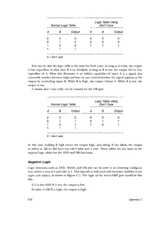
Logic Table Using
                                 Normal Logic Table            Don’t Care

                              A       B      output      A       B      output
                              0       0         0        0       X         0
                              0       1         0        X       0         0
                               1      0         0        1       1         1
                               1      1         1

                              X = don’t care


                     You can see that the logic table is the same for both cases. As long as A is low, the output
                  is low, regardless of what state B is in. Similarly, as long as B is low, the output will be low,
                   regardless of  A.  What  this illustrates is  an  inhibit capability-if   input A  is  a  signal  that
                   constantly switches between high and low, we can control whether the signal appears at the
                   output by  controlling input B.  While B is high, the output follows A.  While  B is low, the
                   output is low.
                     A similar don’t care table can be created for the OR gate:


                                                            Logic Table Using
                                 Normal Logic Table            Don’t Care
                              A       B       Output     A       B      OUtpUt

                              0       0         0        0       0         0
                              0       1         1        X       1         1
                               1      0         1        1       X         1
                               1      1         1

                              X = don’t care


                   In  this case, holding B high forces the  output  high, and  taking B low allows the  output
                   to follow A.  All  we  did here was call 0 false and  1 true. These tables are the same as the
                   original logic tables for the AND and OR functions.


                   Negative Logic
                   Logic functions such as AND, NAND, and OR also can be used in an inverting configura-
                   tion, where a true is 0 and false is 1. This typically is indicated with inversion bubbles at the
                   input and output, as shown in Figure C.l. The logic of  the invert-AND gate would be like
                   this:
                     If A is low AND B is low, the output is low.
                     If either A OR B is high, the output is high.


                   318                                                           Appendix C