
Page 339 - Embedded Microprocessor Systems Real World Design
P. 339
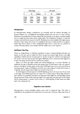
AND Gate                  OR Gate
                               A         B      Output    A        B     output

                               False   False    False    False   False    False
                               False   True     False    False   True     True
                               True    False    False    True    False    True
                               True    True     True     True    True     True


                   Multiplexers
                   In  microprocessor  designs,  multiplexers  are  normally  used  for  address  decoding.  As
                   shown in Figure C.l, a multiplexer has multiple outputs, but only one at a time is active.
                   Multiplexers normally have low-true outputs like the example in the figure, and they usually
                   have an enable line that makes all the outputs false. The multiplexer in Figure C.1 has four
                   outputs, selected with two inputs (A and B). Multiplexers are also available with eight outputs
                   and three select inputs. Of course, if a multiplexer function is implemented in a program-
                   mable logic device (PLD) or other configurable logic device, it may have any number  of
                   outputs with any polarity (even mixed) and the enable may not be required.

                   SetcReset Flip-Flop

                   These are  stmu@ devices. A flipflop remembers its state. A typical  flip-flop will  have  two
                   inputs, set and reset,  and an output, Q. When set goes low, Q goes high. Q then stays high
                   regardless of which state the set input goes to. Q does not go low until the reset input goes
                   low. Q then stays low until set goes low again. Flip-flops can be constructed with high/true
                   or low/true  inputs and inverted or noninverted outputs.
                      Figure  C.2  shows  the  logic  symbol  and  timing  diagram  for  a  set/reset  flipflop.  As
                   indicated, this type of flipflop can be built using a pair of NAND gates. Only one output is
                   shown in the figure, but the output of the other NAND gate also can be used and will be an
                   inverting output. A pair of NOR gates wired the same way as Figure C.2 also will function as
                   a flip-flop, but the inputs will be high/true  instead of low/true.
                      So what happens if both inputs to a NAND flip-flop go low at the same time? If you look
                   at the logic, both NAND  gates have one input low, so both outputs will go high. However,
                   this condition is not latched, and when one input goes back high, the corresponding output
                   will go back low. If both of the inputs go high at the same time, the final state of the output
                   will be indeterminate. A similar result occurs in a NOR flip-flop; if both inputs are taken
                   high, both outputs go low.


                                             Registers and Latches

                   Microprocessor circuits  invariably require  some  kind  of  registered  logic.  This  often  is
                   embedded in the peripheral ICs connected to the processor. However, often some form of


                   320                                                            Appendix C