
Page 340 - Embedded Microprocessor Systems Real World Design
P. 340
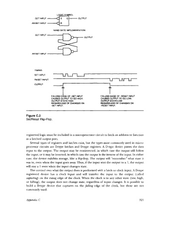
LOGIC SYMBOL
                      -SET INPUT  *
                                                 OUTPUT
                    -RESET INPUT
                                 NAND GATE IMPLEMENTATION
                      -SET INPUT
                                                    OUTPUl


                    -RESET INPUT


                      TIMING
                      SET INPUT
                      RESET INPUT                                   U
                      OUTPUT           I                            1
                                                                   f

                                FALLING E 1 OF -SET INPUT     FALLING EDGE OF -RESET INPUT
                                        GE
                                CAUSES OUTPUT TO GO HIGH.     CAUSES OUTPUT TO GO LOW.
                                OUTPUT STAYS HIGH             OUTPUT STAYS LOW
                                REGARDLESS OF CHANGES ON      REGARDLESS OF CHANGES ON
                                -SET INPUT.                   -RESET INPUT.
                 Figure C.2
                 SeVReset Flip-Flop.


                 registered logic must be included in a microprocessor circuit to latch an address or function
                 as a latched output port.
                   Several types of registers and latches exist, but the types most commonly used in micro-
                 processor circuits are D-type latches and D-type registers. A D-type device  passes  the data
                 input to the output. The output may be noninverted, in which  case the output will follow
                 the input, or it may be inverted, in which case the output is the inverse of the input. In either
                 case, the device exhibits storage, like a flip-flop. The output will  “remember” what state it
                 was in, even when the input goes away. Thus, if the input sent the output to a 1, the output
                 will stay a 1 even when the input changes state.
                   The control over what the output does is performed with a latch or clock input. A D-type
                 registered  device  has  a  clock  input  and  will  transfer  the  input  to  the  output  (called
                 capturing) on the rising edge of  the clock. When the clock is in any other state (low, high,
                 or falling), the output does not change state, regardless of input changes. It is possible to
                 build  a  D-type  device  that  captures on  the fulling edge  of  the  clock, but  these  are  not
                 commonly used.


                 Appendix C                                                           321