
Page 349 - Embedded Microprocessor Systems Real World Design
P. 349
OUTPUT
REGISTER BWK V
Y-REGISTER CONTROL INWS
1 H ADORES 10 BITS BlTse.18 2-REGISTER CONTROL lNRlTs f MU CONTROL INFliTS
BIT 10
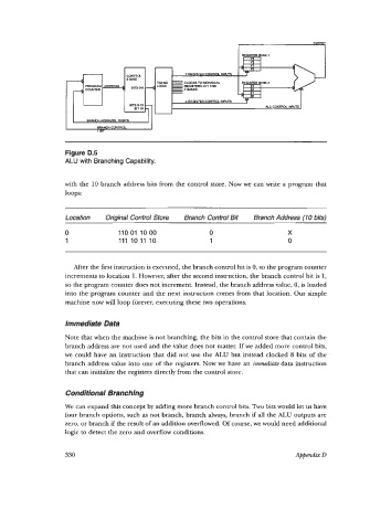
Figure D.5
ALU with Branching Capability.
with the 10 branch address bits from the control store. Now we can write a program that
loops:
Location Original Control Store Branch Control Bit Branch Address (10 bits)
0 11001 1000 0 X
1 111 10 11 10 1 0
After the first instruction is executed, the branch control bit is 0, so the program counter
increments to location 1. However, after the second instruction, the branch control bit is 1,
so the program counter does not increment. Instead, the branch address value, 0, is loaded
into the program counter and the next instruction comes from that location. Our simple
machine now will loop forever, executing these two operations.
Immediate Data
Note that when the machine is not branching, the bits in the control store that contain the
branch address are not used and the value does not matter. If we added more control bits,
we could have an instruction that did not use the ALU but instead clocked 8 bits of the
branch address value into one of the registers. Now we have an immediate data instruction
that can initialize the registers directly from the control store.
Conditional Branching
We can expand this concept by adding more branch control bits. Two bits would let us have
four branch options, such as not branch, branch always, branch if all the ALU outputs are
zero, or branch if the result of an addition overflowed. Of course, we would need additional
logic to detect the zero and overflow conditions.
330 Appendix D