
Page 90 - Embedded Microprocessor Systems Real World Design
P. 90
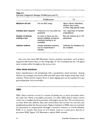
Table 2.2
                  Summary Comparison Between SPI/Microwire and I'C.

                                              SPNMicro wire                  I'C

                  Maximum bit rate      Into the MHz range         About 100 kHz (standard),
                                                                   400 kHz (fast mode),
                                                                   3.4MHz  (high-speed mode)
                  Interface pins required   Three plus one chip select per   Two, regardless of  number
                                        peripheral                 of peripherals
                  Number of devices     As many as there are chip   Bus can address up to 127
                  sharing a bus         selects available, as long as   peripherals
                                        maximum loading is not
                                        exceeded
                  Interface method      Usually dedicated hardware,   Software, but hardware ICs
                                        can be implemented in      are available
                                        software


                    Also note that many SPI/Microwire devices perform operations, such as latch-
                  ing previously written data, on the rising edge of -CS.  Consequently, the -CS  signal
                  must remain stable throughout the access cycle.

                  Other Serial Interfaces

                  Some manufacturers  sell peripherals with  a  proprietary  serial interface.  Analog
                  Devices, for example, has several  ADC and DAC parts with simple serial data/clock
                  schemes. These devices require three or more signals and can be interfaced to any
                  general-purpose microcontroller.


                  DMA

                  DMA  (direct memory access) is a means of having two or more processors share
                  the same bus. When a secondary processor  (or other DMA device) wants control
                  of the bus, it notifies the first processor, which gives up the bus. The second proces-
                  sor then drives the address, data, and control lines and accesses the memory and
                  peripherals just like the first processor. Typical examples of DMA uses are to permit
                  two processors to communicate through a common memory, to refresh dynamic
                  RAM,  or to  transfer data from an 1/0 device  (such as a serial port)  directly to
                  processor RAM. Figure 2.22 illustrates a typical DMA transfer.


                  74                                              Embedded Micr@-rocessor Systm