
Page 69 - Academic Press Encyclopedia of Physical Science and Technology 3rd BioTechnology
P. 69
P1: GRB Final Pages
Encyclopedia of Physical Science and Technology EN002G-67 May 25, 2001 20:8
Bioreactors 251
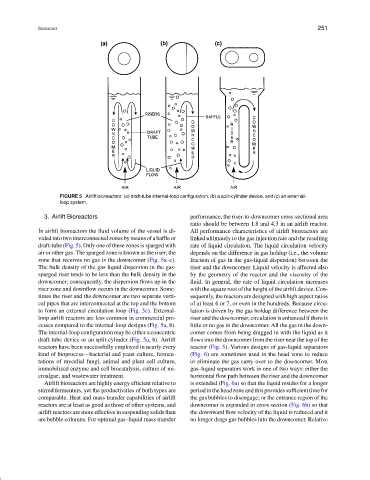
FIGURE 5 Airlift bioreactors: (a) draft-tube internal-loop configuration, (b) a split-cylinder device, and (c) an external-
loop system.
3. Airlift Bioreactors performance, the riser-to-downcomer cross-sectional area
ratio should be between 1.8 and 4.3 in an airlift reactor.
In airlift bioreactors the fluid volume of the vessel is di- All performance characteristics of airlift bioreactors are
videdintotwointerconnectedzonesbymeansofabaffleor linked ultimately to the gas injection rate and the resulting
draft-tube (Fig. 5). Only one of these zones is sparged with rate of liquid circulation. The liquid circulation velocity
air or other gas. The sparged zone is known as the riser; the depends on the difference in gas holdup (i.e., the volume
zone that receives no gas is the downcomer (Fig. 5a–c). fraction of gas in the gas-liquid dispersion) between the
The bulk density of the gas-liquid dispersion in the gas- riser and the downcomer. Liquid velocity is affected also
sparged riser tends to be less than the bulk density in the by the geometry of the reactor and the viscosity of the
downcomer; consequently, the dispersion flowsupinthe fluid. In general, the rate of liquid circulation increases
riser zone and downflow occurs in the downcomer. Some- with the square root of the height of the airlift device. Con-
times the riser and the downcomer are two separate verti- sequently, the reactors are designed with high aspect ratios
cal pipes that are interconnected at the top and the bottom of at least 6 or 7, or even in the hundreds. Because circu-
to form an external circulation loop (Fig. 5c). External- lation is driven by the gas holdup difference between the
loop airlift reactors are less common in commercial pro- riser and the downcomer, circulation is enhanced if there is
cesses compared to the internal-loop designs (Fig. 5a, b). little or no gas in the downcomer. All the gas in the down-
The internal-loop configuration may be either a concentric comer comes from being dragged in with the liquid as it
draft-tube device or an split-cylinder (Fig. 5a, b). Airlift flows into the downcomer from the riser near the top of the
reactors have been successfully employed in nearly every reactor (Fig. 5). Various designs of gas-liquid separators
kind of bioprocess—bacterial and yeast culture, fermen- (Fig. 6) are sometimes used in the head zone to reduce
tations of mycelial fungi, animal and plant cell culture, or eliminate the gas carry over to the downcomer. Most
immobilized enzyme and cell biocatalysis, culture of mi- gas–liquid separators work in one of two ways: either the
croalgae, and wastewater treatment. horizontal flow path between the riser and the downcomer
Airlift bioreactors are highly energy efficient relative to is extended (Fig. 6a) so that the liquid resides for a longer
stirred fermenters, yet the productivities of both types are period in the head zone and this provides sufficient time for
comparable. Heat and mass transfer capabilities of airlift the gas bubbles to disengage; or the entrance region of the
reactors are at least as good as those of other systems, and downcomer is expanded in cross section (Fig. 6b) so that
airlift reactors are more effective in suspending solids than the downward flow velocity of the liquid is reduced and it
are bubble columns. For optimal gas–liquid mass transfer no longer drags gas bubbles into the downcomer. Relative