
Page 276 - Academic Press Encyclopedia of Physical Science and Technology 3rd Chemical Engineering
P. 276
P1: GLM/GLT P2: GLM Final
Encyclopedia of Physical Science and Technology En006G-249 June 27, 2001 14:7
68 Fluid Dynamics (Chemical Engineering)
arepublishedbymanufacturersoffittingsandvalves.They
are much too extensive to be reproduced here.
C. Noncircular Ducts
The mathematical analysis of flow in ducts of noncircular
cross section is vastly more complex in laminar flow than
for circular pipes and is impossible for turbulent flow.Asa
result, relatively little theoretical base has been developed
for the flow of fluids in noncircular ducts. In order to deal
with such flows practically, empirical methods have been
developed.
The conventional method is to utilize the pipe flow
relations with pipe diameter replaced by the hydraulic
diameter,
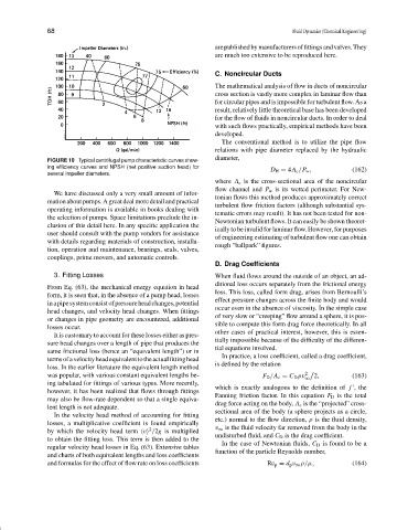
FIGURE 10 Typical centrifugal pump characteristic curves show-
ing efficiency curves and NPSH (net positive suction head) for D H = 4A c /P w , (162)
several impeller diameters.
where A c is the cross-sectional area of the noncircular
flow channel and P w is its wetted perimeter. For New-
We have discussed only a very small amount of infor-
tonian flows this method produces approximately correct
mationaboutpumps.Agreatdealmoredetailandpractical
turbulent flow friction factors (although substantial sys-
operating information is available in books dealing with
tematic errors may result). It has not been tested for non-
the selection of pumps. Space limitations preclude the in-
Newtonian turbulent flows. It can easily be shown theoret-
clusion of this detail here. In any specific application the
ically to be invalid for laminar flow. However, for purposes
user should consult with the pump vendors for assistance
of engineering estimating of turbulent flow one can obtain
with details regarding materials of construction, installa-
rough “ballpark”figures.
tion, operation and maintenance, bearings, seals, valves,
couplings, prime movers, and automatic controls.
D. Drag Coefficients
3. Fitting Losses When fluid flows around the outside of an object, an ad-
ditional loss occurs separately from the frictional energy
From Eq. (63), the mechanical energy equation in head
loss. This loss, called form drag, arises from Bernoulli’s
form, it is seen that, in the absence of a pump head, losses
effect pressure changes across the finite body and would
inapipesystemconsistofpressureheadchanges,potential
occur even in the absence of viscosity. In the simple case
head changes, and velocity head changes. When fittings
of very slow or “creeping”flow around a sphere, it is pos-
or changes in pipe geometry are encountered, additional
sible to compute this form drag force theoretically. In all
losses occur.
other cases of practical interest, however, this is essen-
It is customary to account for these losses either as pres-
tially impossible because of the difficulty of the differen-
sure head changes over a length of pipe that produces the
tial equations involved.
same frictional loss (hence an “equivalent length”)orin
In practice, a loss coefficient, called a drag coefficient,
termsofavelocityheadequivalenttotheactualfittinghead
is defined by the relation
loss. In the earlier literature the equivalent length method
was popular, with various constant equivalent lengths be- F D /A c = C D ρv 2 2, (163)
∞
ing tabulated for fittings of various types. More recently,
which is exactly analogous to the definition of f , the
however, it has been realized that flows through fittings
Fanning friction factor. In this equation F D is the total
may also be flow-rate dependent so that a single equiva-
drag force acting on the body, A c is the “projected” cross-
lent length is not adequate.
sectional area of the body (a sphere projects as a circle,
In the velocity head method of accounting for fitting
etc.) normal to the flow direction, ρ is the fluid density,
losses, a multiplicative coefficient is found empirically
2
by which the velocity head term v /2g is multiplied v ∞ is the fluid velocity far removed from the body in the
undisturbed fluid, and C D is the drag coefficient.
to obtain the fitting loss. This term is then added to the
In the case of Newtonian fluids, C D is found to be a
regular velocity head losses in Eq. (63). Extensive tables
function of the particle Reynolds number,
and charts of both equivalent lengths and loss coefficients
and formulas for the effect of flow rate on loss coefficients Re p = d p v ∞ ρ/µ, (164)