
Page 274 - Academic Press Encyclopedia of Physical Science and Technology 3rd Chemical Engineering
P. 274
P1: GLM/GLT P2: GLM Final
Encyclopedia of Physical Science and Technology En006G-249 June 27, 2001 14:7
66 Fluid Dynamics (Chemical Engineering)
HHP = p f (psi)Q(gpm)/1714, (159) all control points and to terminate on the terminal mp.
In this example no more PSs are required, and the HGL
while the actual horsepower (AHP) is HHP divided by
terminates at mp-105 at a head of 4240 ft. This is far too
the pump efficiency (here taken to be 0.75; actual values
much head for the specified conditions of the design. The
would be fixed by the vendor in a real case).
excess head (4240–1600 ft) must be consumed as friction,
9. The nominal horsepower per pump station (HP/PS)
as already explained. In Fig. 8 the diameter is decreased
is fixed. This is done by rounding the AHP/PS up to the
to a 6-in, pipe at mp-79.2. This introduces the HGL for
next nearest 50 hp.
the 6-in. pipe, which now terminates at 1600 ft at mp-105
10. Theactualheadrequiredisdetermined.Thisisdone
as desired.
by taking the nominal HP/PS and computing the pump
13. The system is optimized. Steps 1–12 must be re-
station pressure rise from Eq. (159).
peated for each candidate pipe. The entire set must then
11. The PS discharge head is determined. This is done
be cost optimized. For example, the design indicated by
by adding to the PS pressure rise just computed the net
Fig. 8 will work hydraulically but is not optimum. We
positive suction head (NPSH) of the pump as specified by
see that at mp-60, the interior control point, we have ac-
the vendor. It is always wise to allow an additional head
tually cleared GP by 342 ft. This is considerably more
above this value as a safety factor. Here a 50-ft intake head
than the minimum 50-ft terrain clearance required and is
has been assumed for illustrative purposes.
therefore wasteful of pumpinig energy. The design can ob-
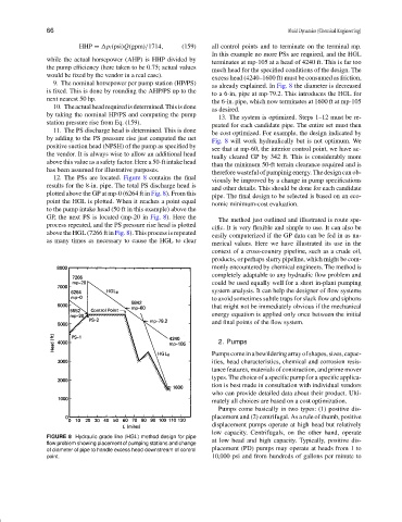
12. The PSs are located. Figure 8 contains the final
viously be improved by a change in pump specifications
results for the 8-in. pipe. The total PS discharge head is
and other details. This should be done for each candidate
plotted above the GP at mp-0 (6264 ft in Fig. 8). From this
pipe. The final design to be selected is based on an eco-
point the HGL is plotted. When it reaches a point equal
nomic minimum-cost evaluation.
to the pump intake head (50 ft in this example) above the
GP, the next PS is located (mp-20 in Fig. 8). Here the
The method just outlined and illustrated is route spe-
process repeated, and the PS pressure rise head is plotted
cific. It is very flexible and simple to use. It can also be
above the HGL (7266 ft in Fig. 8). This process is repeated
easily computerized if the GP data can be fed in as nu-
as many times as necessary to cause the HGL to clear
merical values. Here we have illustrated its use in the
context of a cross-country pipeline, such as a crude oil,
products, or perhaps slurry pipeline, which might be com-
monly encountered by chemical engineers. The method is
completely adaptable to any hydraulic flow problem and
could be used equally well for a short in-plant pumping
system analysis. It can help the designer of flow systems
to avoid sometimes subtle traps for slack flow and siphons
that might not be immediately obvious if the mechanical
energy equation is applied only once between the initial
and final points of the flow system.
2. Pumps
Pumpscomeinabewilderingarrayofshapes,sizes,capac-
ities, head characteristics, chemical and corrosion resis-
tance features, materials of construction, and prime mover
types. The choice of a specific pump for a specific applica-
tion is best made in consultation with individual vendors
who can provide detailed data about their product. Ulti-
mately all choices are based on a cost optimization.
Pumps come basically in two types: (1) positive dis-
placement and (2) centrifugal. As a rule of thumb, positive
displacement pumps operate at high head but relatively
low capacity. Centrifugals, on the other hand, operate
FIGURE 8 Hydraulic grade line (HGL) method design for pipe
flow problem showing placement of pumping stations and change at low head and high capacity. Typically, positive dis-
of diameter of pipe to handle excess head downstream of control placement (PD) pumps may operate at heads from 1 to
point. 10,000 psi and from hundreds of gallons per minute to