
Page 273 - Academic Press Encyclopedia of Physical Science and Technology 3rd Chemical Engineering
P. 273
P1: GLM/GLT P2: GLM Final
Encyclopedia of Physical Science and Technology En006G-249 June 27, 2001 14:7
Fluid Dynamics (Chemical Engineering) 65
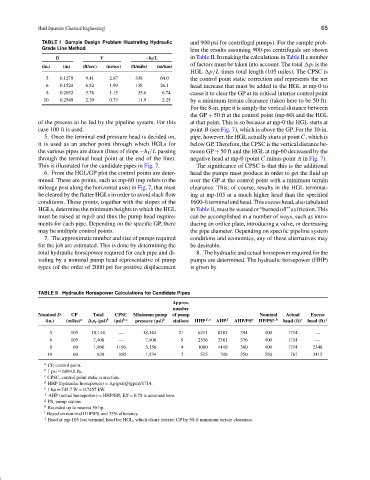
TABLE I Sample Design Problem Illustrating Hydraulic and 900 psi for centrifugal pumps). For the sample prob-
Grade Line Method lem the results assuming 900-psi centrifugals are shown
D V −h f /L in Table II. In making the calculations in Table II a number
of factors must be taken into account. The total p f is the
(in.) (m) (ft/sec) (m/sec) (ft/mile) (m/km)
HGL p/L times total length (105 miles). The CPSC is
5 0.1270 9.41 2.87 338 64.0 the control point static correction and represents the net
6 0.1524 6.52 1.99 138 26.1 head increase that must be added to the HGL at mp-0 to
8 0.2032 3.76 1.15 35.6 6.74 cause it to clear the GP at its critical interior control point
10 0.2540 2.39 0.73 11.9 2.25 by a minimum terrain clearance (taken here to be 50 ft).
For the 8-in. pipe it is simply the vertical distance between
the GP + 50 ft at the control point (mp-60) and the HGL
of the process to be fed by the pipeline system. For this at that point. This is so because at mp-0 the HGL starts at
case 100 ft is used. point B (see Fig. 7), which is above the GP. For the 10-in.
5. Once the terminal end pressure head is decided on, pipe, however, the HGL actually starts at point C, which is
it is used as an anchor point through which HGLs for below GP. Therefore, the CPSC is the vertical distance be-
the various pipes are drawn (lines of slope −h f /L passing tween GP + 50 ft and the HGL at mp-60 decreased by the
through the terminal head point at the end of the line). negative head at mp-0 (point C minus point A in Fig. 7).
This is illustrated for the candidate pipes in Fig. 7. The significance of CPSC is that this is the additional
6. From the HGL/GP plot the control points are deter- head the pumps must produce in order to get the fluid up
mined. These are points, such as mp-60 (mp refers to the over the GP at the control point with a minimum terrain
mileage post along the horizontal axis) in Fig. 7, that must clearance. This, of course, results in the HGL terminat-
be cleared by the flatter HGLs in order to avoid slack flow ing at mp-105 at a much higher head than the specified
conditions. These points, together with the slopes of the 1600-ftterminalendhead.Thisexcesshead,alsotabulated
HGLs, determine the minimum heights to which the HGL in Table II, must be wasted or “burned off” as friction. This
must be raised at mp-0 and thus the pump head require- can be accomplished in a number of ways, such as intro-
ments for each pipe. Depending on the specific GP, there ducing an orifice plate, introducing a valve, or decreasing
may be multiple control points. the pipe diameter. Depending on specific pipeline system
7. The approximate number and size of pumps required conditions and economics, any of these alternatives may
for the job are estimated. This is done by determining the be desirable.
total hydraulic horsepower required for each pipe and di- 8. The hydraulic and actual horsepower required for the
viding by a nominal pump head representative of pump pumps are determined. The hydraulic horsepower (HHP)
types (of the order of 2000 psi for positive displacement is given by
TABLE II Hydraulic Horsepower Calculations for Candidate Pipes
Approx.
number
Nominal D CP Total CPSC Minimum pump of pump Nominal Actual Excess
(in.) (miles) a ∆p f (psi) b (psi) b,c pressure (psi) b stations HHP d,e AHP f AHP/PS g HP/PS g,h head (ft) i head (ft) j
5 105 18,144 — 18,144 21 6211 8281 394 400 1714 —
6 105 7,408 — 7,408 9 2536 3381 376 400 1714 —
8 60 1,960 1196 3,156 4 1080 1440 360 400 1714 2348
10 60 639 895 1,534 2 525 700 350 350 767 3415
a
CP, control point.
b
1 psi ≡ 6894.8 Pa.
c
CPSC, control point static correction.
d
HHP (hydraulic horsepower) = p(psi)Q(gpm)/1714.
e
1hp ≡ 745.7 W = 0.7457 kW.
f
AHP (actual horsepower) = HHP/Eff; Eff = 0.75 is assumed here.
g PS, pump station.
h Rounded up to nearest 50 hp.
i Based on nominal HHP/PS and 75% efficiency.
j Head at mp-105 less terminal head for HGL, which clears interior CP by 50-ft minimum terrain clearance.