
Page 275 - Academic Press Encyclopedia of Physical Science and Technology 3rd Chemical Engineering
P. 275
P1: GLM/GLT P2: GLM Final
Encyclopedia of Physical Science and Technology En006G-249 June 27, 2001 14:7
Fluid Dynamics (Chemical Engineering) 67
a fraction of a gallon per minute depending on the con- pump, V R is the volume displaced by the rod in the double-
ditions. Typical centrifugal pumps may operate at heads acting case, N is the number of cylinders per pump, and
of a few tens of feet to several hundreds of feet and ca- e is a volumetric efficiency factor, usually 0.95–0.99.
pacities of several thousands of gallons per minute. It is The total volumetric capacity of the pump is
possible to operate PD pumps in parallel or centrifugal
Q = ωQ , (161)
pumps in series to achieve high head and high capacity.
Some pump manufacturers also make “staged” centrifugal where ω is the frequency in strokes per time. As an illus-
pumps, which are essentially multiple centrifugal pumps tration of the use of these equations, suppose that in the
of identical head characteristics mounted on a common previous HGL sample design problem we had elected to
shaft and plumbed so as to permit the discharge of one to use single-acting (n = 1, V R = 0), triplex (N = 3) piston
be the intake of the next stage. pumps with a 12-in. piston diameter and a 10-in. stroke.
At a total throughput of 587 gpm we calculate Q = 3256
3
a. Positive displacement pumps. Positive dis- in. /stroke from Eq. (160) and from Eq. (161) we find
placement pumps include gear pumps, piston pumps, ω = 41.6 strokes per/minute. Armed with such informa-
plunger pumps, and progressing cavity pumps. All PD tion one can now seek a specific vendor. Adjustments in
pumps have in common the fact that they are volumetric several of the design variables may need to be made to be
devices in which a fixed volume of fluid is drawn into the compatible with vendor specifications.
pump, pressurized, and discharged at high pressure into A useful feature of the PD pump is that for a given power
the line. As a result, the output is pulsatile, giving rise to a input Eqs. (159)–(161) allow the designer considerable
(sometimes violently) fluctuating discharge pressure. This flexibility in adjusting discharge pressure, cylinder capac-
necessitates the installation of pulsation dampeners at the ity, and overall capacity. Positive displacement pumps are
discharge of all PD pumps in a large pumping installation favorites on large-scale, high-pressure systems. Details of
to protect the system against heavy pressure surging. each of the various types of PD pump are best obtained
Another feature of PD pumps is that, if the line for from individual vendors.
any reason becomes blocked, they simply continue forc-
ing high-pressure fluid into the line and eventually break b. Centrifugal pumps. The operation of centrifugal
something if a precautionary rupture system has not been pumps is entirely different from that of PD pumps. The
installed. Thus, a PD pump should be protected by a high- principle of operation involves spinning a circular vaned
pressure shutoff sensor and alarm system and also a bypass disk at high speed inside a casing. The resulting cenrifugal
line containing a rupture disk or pressure relief valve. force accelerates the fluid to high velocity at the tangen-
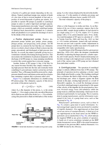
Figure 9 is a schematic illustration of a double-acting tial discharge port, where it stagnates against the fluid
PD piston pump. The volumetric capacity of this device already in the pipe, creating high pressure as a result of
per stroke of the piston is given by Bernoulli’s equation. As a result the discharge pressure
of an ideal centrifugal pump is proportional to the square
1 2
Q = π D L s n − V R Ne, (160)
4 p of the velocity of the impeller tip. In actual practice, how-
where D p is the diameter of the piston, L s is the stroke ever, frictional energy losses and turbulence within the
length,n = 1forasingle-acting(onlyonesideofthepiston pump result in a different relationship, which must be de-
drives fluid on one-half of the stroke) or n = 2 for a double- termined experimentally for each pump. This is routinely
acting (the piston drives fluid on both halves of the stroke) done by pump manufacturers, and the information is pre-
sented in the form of a pump head curve, such as that
illustrated in Fig. 10.
Manufacturers’ performance curves, such as those in
Fig. 10, contain a great deal of useful information. Ac-
tual average head–capacity curves are shown for a number
of impeller diameters. Also superimposed on these head
curves are curves of constant efficiency. A third set of cur
ves superimposed on the head curves are the NPSH re-
quirement curves (dashed line in Fig. 10), which indicate
the required NPSH at any given condition of operation.
A fourth set of curves sometimes included are the BHP
(brake horsepower) curves. BHP is the actual horsepower
calculated in the previous HGL method illustration. It is
FIGURE 9 Schematic illustration of double-acting piston pump. the HHP divided by the effciency.