
Page 121 - Academic Press Encyclopedia of Physical Science and Technology 3rd Polymer
P. 121
P1: FMX/LSU P2: GPB/GRD P3: GLQ Final pages
Encyclopedia of Physical Science and Technology EN012c-593 July 26, 2001 15:56
Polymer Processing 627
ratio for the two modes of bursting, i.e., tip streaming Continuous compounders are for the most part designed
(for p < 0.1) and regular bursting. Tip streaming refers to around one or more extruders, either of the single- or twin-
the situation where droplets assume a sigmoidal shape screw type. The most versatile screw-extruder compound-
with tiny droplets shedding off the tops. The important ing lines are the so-called two-stage compounding lines,
feature shown in Fig. 20 is the inability of shear flows to which combine high-performance continuous melt mix-
cause droplet breakup at viscosity ratios exceeding 3.5, ers, such as planetary gear extruders, twin-screw extrud-
while for shear-free flows (i.e., extensional flow) breakup ers, twin-rotor continuous mixers, and reciprocating screw
occurs over a wide range of viscosity ratios. kneaders, with a single-screw extruder. These melt mixers
provide excellent control over shear, stock temperature,
dwell time, and homogeneity. The second stage, usually a
B. Commercial Compounding Lines short single-screw extruder, receives the melt and meters
it to a strand die. Vacuum venting is normally available in
Compounding lines fall into two broad categories: batch
the transition area between the extruders, which ensures
and continuous systems. A commonly used batch mixer
that any volatile matter is extracted from the plastics. Nor-
is the Banbury high-intensity internal mixer shown in
mally, both extruders have separate drive motors and the
Fig. 21. It consists of a figure-eight-shaped chamber with
capacity to vary the compounding rpms independently of
two rotors that rotate in a counterrotating direction. The
metering.
materials to be mixed are fed through the hopper door and
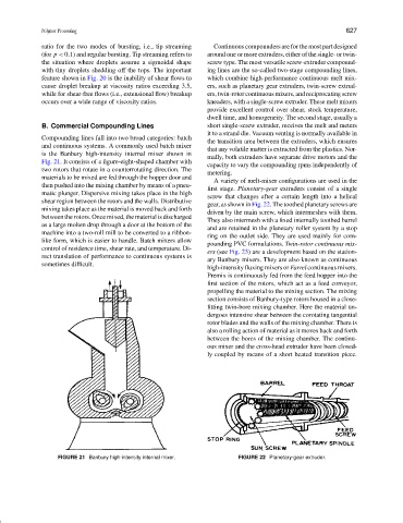
A variety of melt-mixer configurations are used in the
then pushed into the mixing chamber by means of a pneu-
first stage. Planetary-gear extruders consist of a single
matic plunger. Dispersive mixing takes place in the high
screw that changes after a certain length into a helical
shear region between the rotors and the walls. Distributive
gear, as shown in Fig. 22. The toothed planetary screws are
mixing takes place as the material is moved back and forth
driven by the main screw, which intermeshes with them.
between the rotors. Once mixed, the material is discharged
They also intermesh with a fixed internally toothed barrel
as a large molten drop through a door at the bottom of the
and are retained in the planetary roller system by a stop
machine into a two-roll mill to be converted to a ribbon-
ring on the outlet side. They are used mainly for com-
like form, which is easier to handle. Batch mixers allow
pounding PVC formulations. Twin-rotor continuous mix-
control of residence time, shear rate, and temperature. Di-
ers (see Fig. 23) are a development based on the station-
rect translation of performance to continuous systems is
ary Banbury mixers. They are also known as continuous
sometimes difficult.
high-intensity fluxing mixers or Farrel continuous mixers.
Premix is continuously fed from the feed hopper into the
first section of the rotors, which act as a feed conveyor,
propelling the material to the mixing section. The mixing
section consists of Banbury-type rotors housed in a close-
fitting twin-bore mixing chamber. Here the material un-
dergoes intensive shear between the corotating tangential
rotor blades and the walls of the mixing chamber. There is
also a rolling action of material as it moves back and forth
between the bores of the mixing chamber. The continu-
ous mixer and the cross-head extruder have been closed-
ly coupled by means of a short heated transition piece.
FIGURE 21 Banbury high-intensity internal mixer. FIGURE 22 Planetary-gear extruder.