
Page 116 - Academic Press Encyclopedia of Physical Science and Technology 3rd Polymer
P. 116
P1: FMX/LSU P2: GPB/GRD P3: GLQ Final pages
Encyclopedia of Physical Science and Technology EN012c-593 July 26, 2001 15:56
622 Polymer Processing
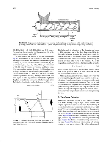
FIGURE 16 Single-screw plasticating extruder showing the four primary zones: hopper, solids feed, melting, and
pumping. [From Baird, D. G., and Collias, D. I. (1998). “Polymer Processing: Principles and Design,” Wiley, New York.]
8.0, 10.0, 12.0, 14.0, 16.0, 18.0, 20.0, and 24.0 inches. The helix angle is a function of the diameter and hence
The length to diameter ratios (L /D) range from 20 to 30, is different at the base of the flight than at the flight tip.
but the most common ratio is 24. The radial distance between the barrel surface and the
The main geometrical features of a screw are shown in root of the screw is the channel depth. The main design
Fig. 17. The diameter of the screw at the tip of the flight variable of screws is the channel depth profile along the
(the flight is the metal that remains after machining the helical direction. The width of the channel, W, is the
channel), D s , is less than the diameter of the barrel, D b , by perpendicular distance between the flights and is given by
an amount 2δ f (i.e., D s = D b −2δ f ), where δ f is of the order
W = L s cos φ − e , (26)
of 0.2–0.5 mm. Of course, as the screw and barrel wear,
δ f increases and the leakage flow over the flights increases where e is the flight width. We note here that W varies
to the point where the screw loses its pumping efficiency. with radial position, and it is also a function of the
The lead of the screw, L s , is the axial distance covered in distance from the root of the screw.
completing one full turn along the flight of the screw. The Although the main function of the single-screw extruder
helix angle, φ, is the angle formed between the flight and is to melt and pump polymer, it has a number of other ap-
the plane normal to the screw axis. The helix angle at the plications. Extruders can be used to remove volatiles such
flight tip is related to the lead and diameter as follows: as water or trace amounts of monomers. They can be used
to generate foamed polymers because the temperature and
tan φ s = L s /π D s . (25)
pressure history can be controlled. They also serve as con-
tinuous mixing and compounding devices. Hence, extrud-
ers have a wider range of applications than other pumping
devices.
B. Twin-Screw Extruders
Twin-screw extruders consist of two screws mounted
in a barrel having a “figure-eight” cross section. The
“figure-eight” cross section comes from the machining of
two cylindrical bores whose centers are less than two radii
apart. Twin-screw extruders are classified by the degree to
which the screws intermesh and the direction of rotation of
the screws. Figure 18 shows three types of screw arrange-
ments. Figure 18a shows an intermeshing counterrotating
type, whereas Fig. 18b shows a corotating intermeshing
type. Figure 18c shows a nonintermeshing counterrotat-
FIGURE 17 Geometrical aspects of a screw. [From Baird, D. G.,
and Collias, D. I. (1998). “Polymer Processing: Principles and De- ing type. Figure 19a shows an intermeshing self-wiping
sign,” Wiley, New York.] corotating twin-screw extruder. Not all the elements of