
Page 100 - Engineered Interfaces in Fiber Reinforced Composites
P. 100
Chapter 3. Measurements of interfacelinterlaminar properties 83
1 Y
t h,l
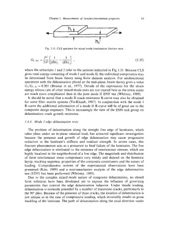
Fig. 3.33. CLS specimen for mixed mode interlaminar fracture tests.
(3.35)
where the subscripts 1 and 2 refer to the sections indicated in Fig 3.33. Because CLS
gives total energy consisting of mode I and mode 11, the individual components may
be determined from beam theory using finite element analysis, For unidirectional
specimens with the delamination placed at the mid-plane, beam theory gives a value
GI/GI-II = 0.205 (Brussat et al., 1977). Details of the expressions for the strain
energy release rate of other mixed-mode tests are not treated here as the stress states
are much more complicated than in the pure mode I1 ENF test (Whitney, 1989).
It should be noted that a mode I1 crack-resistance R-curve may also be obtained
for some fiber-matrix systems (Vu-Khanh, 1987). In conjunction with the mode I
R-curve the additional information of a mode I1 R-curve will be of great use to the
composite design engineers. This is increasingly the view of the ESfS task group on
delamination crack growth resistance.
3.4.4. Mode I edge delamination tests
The problem of delamination along the straight free edge of laminates, which
takes place under an in-plane uniaxial load, has attracted significant investigation
because the presence and growth of edge delamination may cause progressive
reduction in the laminate's stiffness and residual strength. In severe cases, this
fracture phenomenon acts as a precursor to final failure of the laminates. The free
edge delamination is attributed to the existence of interlaminar stresses, which are
highly localized in the neighborhood of a free edge. The magnitude and distribution
of these interlaminar stress components vary widely and depend on the laminate
layup, stacking sequence, properties of the composite constituents and the nature of
loading. Comprehensive reviews of the experimental observations have been
presented (Kim, 1989) and a micromechanics analysis of the edge delamination
test (EDT) has been performed (Whitney, 1989).
Due to the complex mixed-mode nature of composite delamination, no closed
form solutions have been developed yet to express the influence of governing
parameters that control the edge delamination behavior. Under tensile loading,
delamination is normally preceded by a number of transverse cracks, particularly in
the 90" plies. Because of the presence of these cracks, the location of delamination is
not unique as in the case of compressive loading, which invariably results in gross
buckling of the laminate. The path of delamination along the axial direction varies