
Page 97 - Engineered Interfaces in Fiber Reinforced Composites
P. 97
80 Engineered interfaces in fiber reinforced composites
P2
GI, = - kna”-‘ . (3.27)
2b
Further combining Eqs. (3.17) and (3.26), Eq. (3.27) can be rewritten in terms of
displacement, 6
nP6
GI, = - (3.28)
2ba ’
which is the expression for the ‘compliance calibration’ (CC) method suggested by
the specification (ASTM D5528, 1994) and the European Structural Integrity
Society, TC4 Group as a Protocol (1990). A further modification is made to the
“compliance method” given by Eq. (3.28), i.e., ‘modified compliance calibration’
(MCC) method (ASTM D5528, 1994):
(3.29)
where the coefficient a1 is obtained from the slope of the least squares line fit of the
plot of a/h versus C’/3. It is noted in the specification (ASTM D 5528, 1994)
(O’Brien and Martin, 1993) that GI, values determined by the three methods of data
reduction, i.e. MBT, CC and MCC methods, differ by no more than 3.1 % , while the
MBT data reduction method yields the most conservative value of Gtc for 80% of
the specimens tested.
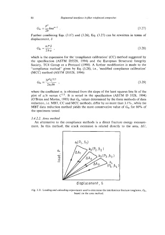
3.4.2.2. Area method
An alternative to the compliance methods is a direct fracture energy measure-
ment. In this method, the crack extension is related directly to the area, AU,
displacement, 6
Fig. 3.31. Loading and unloading experiments used to determine the interlaminar fracture toughness, GI,,
based on the area method.