
Page 94 - Engineered Interfaces in Fiber Reinforced Composites
P. 94
Chapter 3. Measurements of interfacelinterlaminar properties 77
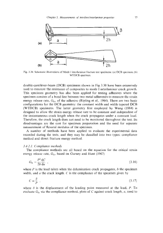
Fig. 3.30. Schematic illustrations of Mode I interlaminar fracture test specimens: (a) DCB specimen; (b)
WTDCB specimen.
double-cantilever-beam (DCB) specimens shown in Fig 3.30 have been extensively
used to measure the resistance of composites to mode I interlaminar crack growth.
This specimen geometry has also been applied for testing adhesives where the
specimen consists of a bond line between two metal adherends to measure the strain
energy release rate, GI,, of the adhesive (Ripling et al., 1964). There are two basic
configurations for the DCB geometry: the constant width and width tapered DCB
(WTDCB) specimens. The latter geometry first employed by Wang (1984) is
designed to allow the strain energy release rate to be constant and independent of
the instantaneous crack length when the crack propagates under a constant load.
Therefore, the crack length does not need to be monitored throughout the test. Its
disadvantages are the cost for specimen preparation and the need for separate
measurement of flexural modulus of the specimen.
A number of methods have been applied to evaluate the experimental data
recorded during the tests, and they may be classified into two types: compliance
method and direct fracture energy method.
3.4.2.1. Compliance methods
The compliance methods are all based on the equation for the critical strain
energy release rate, GI,, based on Gurney and Hunt (1967)
P2 dC
GI, = -- , (3.16)
2b da
where P is the load taken when the delamination crack propagates, b the specimen
width, and a the crack length. C is the compliance of the specimen given by
6
c=- (3.17)
P’
where 6 is the displacement of the loading point measured at the load, P. To
evaluate GI, via the compliance method, plots of C against crack length, a, need to