
Page 92 - Engineered Interfaces in Fiber Reinforced Composites
P. 92
Chapter 3. Meusurements of interfacelinterlaminar properties 75
free notch ply bonded bolted
edge (hole) drop-off joint
\
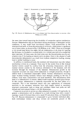
Fig. 3.28. Sources of delamination due to out-of-plane load from discontinuities in structure. After
Wilkins et al. (1982).
the same time toward improving the durability of composites against interlaminar
fracture. Delamination may be introduced during processing or subsequent service
conditions. It may result from low-velocity impact, from eccentricities in the
structural load path, or from discontinuities in structures, which induce a significant
out-of-plane stress, as shown in Fig 3.28 (Wilkins, et al., 1982). These are (i) straight
or (ii) curved (near holes) free edges, (iii) ply terminations or ply drop for tapering
the thickness, (iv) bonded or co-cured joints, (v) a bolted joint and (vi) a cracked lap
shear specimen. All these cases, the local stress near the discontinuities may be out-
of-plane even if the loading at remote end is in-plane. Even in the absence of such
discontinuities delamination can result from in-plane compressive loading, causing
local or global buckling to occur.
In addition to mechanical loads, the moisture and temperature may also induce
interlaminar stresses in a laminate. These may be the results from (i) the residual
thermal stresses caused by cooling from the processing temperatures; and (ii)
residual stresses created by the moisture absorption in the laminate; and (iii)
moisture through the thickness of the laminate. Delamination growth in the
composite structure can cause severe reductions in strength properties, though it
seldom leads to immediate catastrophic failure. Instead, delamination occurring
under in-plane loading normally induces local damages resulting in the loss of
stiffness, local stress concentration and local instability. This delamination often
leads to a redistribution of stresses, which would eventually promote gross failure.
In this context, delamination is indirectly responsible for the final failure of a
composite. This is one important reason why past applications of composite
materials in the aerospace industries have been largely limited to secondary
structural components, such as wings and stabilizers where load paths are well
defined and load-induced failure is not life threatening.
Composite structures in service are often subjected to complex 3-D load paths. In
general, a delamination will be subjected to a crack driving force with a mode I
opening, a mode I1 forward shear and a mode 111 anti-plane shear, as illustrated in
Fig 3.29. Because delamination is constrained to grow between individual plies,
both interlaminar tension and shear stresses are commonly present at the