
Page 89 - Engineered Interfaces in Fiber Reinforced Composites
P. 89
72 Engineered interfaces in jber reinforced composites
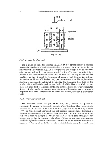
load
-Specimen
-Strain
gauges
1
Fig. 3.24. (b).
3.3.7. In-plane lap-shear test
The in-plane lap-shear test specified in ASTM D 3846 (1985) employs a notched
rectangular specimen of uniform width that is mounted in a supporting jig, as
schematically illustrated in Fig 3.25. A compressive load is applied to the specimen
edge, as opposed to the conventional tensile loading of lap-shear adhesive joints.
Failure of the specimen occurs in the shear between two centrally located notches
machined half-way through its thickness and spaced a fixed distance (Le., 6.4 mm
for specimen thickness of 2.54-6.60 mm) apart on opposite faces. The in-plane shear
strength is subsequently calculated by dividing the maximum shear load by the
product of the width of the specimen and the length of the failed area. While the lap-
shear test lends itself to laminates containing continuous and uniformly distributed
fibers, it is also useful to measure shear strength of laminates having randomly
dispersed short fibers, which cannot be tested satisfactorily by other in-plane shear
tests.
3.3.8. Transverse tensile test
The transverse tensile test (ASTM D 3039, 1982) assesses the quality of
composites by measuring the tensile strength of unidirectional fiber composites in
the direction transverse to the fiber direction (Fig 3.26). Early work by Chamis
(1974) on finite element analysis of this test indicates that interfacial debonding is
the most probable cause of transverse crack initiation. The most obvious feature of
this test is that its strength is usually less than the shear yield strength of the
matrix, z,, so that in contrast to the effect of fibers on the transverse modulus
(which is higher than that of pure matrix material without fibers) the fibers have a
negative reinforcing effect. In the case of a weak interfacial bond, the lower-bound