
Page 88 - Engineered Interfaces in Fiber Reinforced Composites
P. 88
Chapter 3. Measurements of" interfacelinterlaminar properties 71
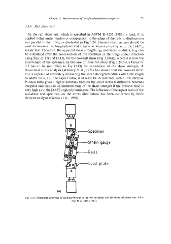
3.3.6. Rail shear test
In the rail shear test, which is specified in ASTM D 4255 (1983), a load, P, is
applied either under tension or compression to the edges of the rails to displace one
rail parallel to the other, as illustrated in Fig 3.24. Element strain gauges should be
used to measure the longitudinal and transverse strains properly as in the [f45"Is
tensile test. Therefore, the apparent shear strength, rI2, and shear modulus, G12, can
be calculated over the cross-section of the specimen in the longitudinal direction
using Eqs. (3.13) and (3.15), for the two-rail shear (Fig 3.24(a)), where b is now the
total length of the specimen. In the case of three-rail shear (Fig 3.24(b)), a factor of
0.5 has to be multiplied to Eq. (3.13) for calculation of the shear strength. A
theoretical stress analysis (Whitney et al., 1971) has shown that the two-rail shear
test is capable of accurately measuring the shear strength/modulus when the length
to width ratio, Le., the aspect ratio, is at least 10. A laminate with a low effective
Poisson ratio gives a higher accuracy because the shear stress distribution becomes
irregular and leads to an underestimate of the shear strength if the Poisson ratio is
very high as in the [f45"] angle ply laminates. The influence of the aspect ratio of the
rail-shear test specimen on the stress distribution has been confirmed by finite
element analysis (Garcia et al., 1980).
Specimen
Strain gauge
Rails
Load plate
Fig. 3.24. Schematic drawings of loading fixtures in (a) two rail shear and (b) three rail shear test. After
ASTM D 4255 (1983).