
Page 86 - Engineered Interfaces in Fiber Reinforced Composites
P. 86
Chapter 3. Measurements of interfacelinterlaminar properties 69
3.3.4. [f45], tensile test
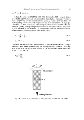
In the [f45], tensile test (ASTM D 3518,1991) shown in Fig 3.22, a uniaxial tension
is applied to a (f45") laminate symmetric about the mid-plane to measure the strains
in the longitudinal and transverse directions, and E~. This can be accomplished by
instrumenting the specimen with longitudinal and transverse element strain gauges.
Therefore, the shear stressstrain relationships can be calculated from the tabulated
values of ex and E,,, corresponding to particular values of longitudinal load, P, (or stress
ox over the width, b, and thickness, t, of the specimen), based on the relations derived
from laminated plate theory (Petit, 1969; Rosen, 1972):
px ax
=
212 = - - (3.13)
2bt 2 '
(3.14)
Y12 = Ex - cy '
Therefore, the unidirectional translaminar (i.e. through-thickness) shear strength
can be obtained for the maximum load and the in-plane shear modulus of elasticity,
GLT, taken from the initial linear portion of the unidirectional shear stress-shear
strain (212 - y12) curve:
(3.15)
t Loading direction
Fig. 3.22. Schematic drawing of specimcn for [&45"], tensile test. After ASTM D 3518. (1991).