
Page 84 - Engineered Interfaces in Fiber Reinforced Composites
P. 84
Chapter 3. Measurements of interfacelinterlaminar properties 67
pi
Loading fixture
1
A L- Specimen
P
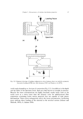
Fig. 3.20. Schematic drawings of loading configurations of (a) Iosipcscu shear test and (b) asymmetric
four-point bending (AFPB) test. After Iosipescu (1967) and Slepetz et al. (1978).
notch angle depending on the type of composites (Fig 3.21). In addition to the depth
and tip radius of the specimen notch, there are other factors to consider in practice.
Because the stress concentrations are highly localized, cracks easily form at the
notch roots at a stress lower than the ultimate value for unidirectional fiber
composites containing brittle matrix materials that are capable of little plastic
deformation. These cracks subsequently relieve the stress concentration, facilitating
more uniform shear loading of the material in the notched section (Adams and
Walrath, 1987a, b; Adams 1990).