
Page 98 - Engineered Interfaces in Fiber Reinforced Composites
P. 98
Chapter 3. Measurements of interfacelinterlaminar properties 81
enclosed between the loading and unloading paths for extension of a known crack
length, Aa, as shown in Fig 3.31. The mode I strain energy release rate is defined by
(3.30)
Therefore, an average value of GI, for an extension of crack length, a2 - al, is
determined by measuring the force, P, and the corresponding displacement, 6.
However, the crack propagation must be stable for reliable application of
Eq. (3.30). If large, unstable crack jumps with precipitous load drops are prevalent,
the above expression becomes invalid due to the kinetic energy lost in the fracture
process. For these reasons, interpretation of DCB test data should always be carried
out in conjunction with an examination of the fracture surface. Further complica-
tion is encountered by the presence of long debonded fibers bridging the cracked
surfaces as mentioned earlier.
3.4.3. Mode 11 interlaminar ,fracture tests
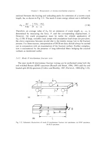
The pure mode I1 interlaminar fracture testing can be performed using both the
end notched flexure (ENF) specimen (Russell and Street, 1984, 1985) and the end
loaded split (ELS) specimen (Corleto and Bradley, 1987; Prel et al., 1989) (Fig 3.32).
I
2L
L
Fig. 3.32. Schematic illustrations of mode I1 interlaminar fracture test specimens: (a) ENF specimen;
(b) ELS specimen.