
Page 101 - Engineered Interfaces in Fiber Reinforced Composites
P. 101
84 Engineered interfaces in jiber reinforced composites
I
Pi
5O
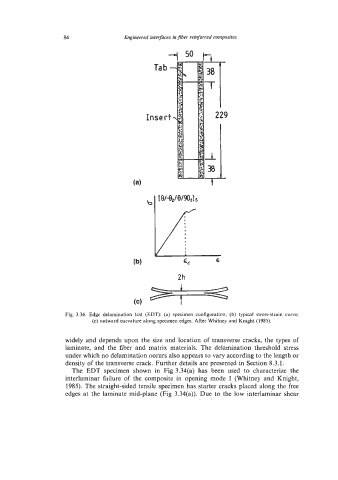
Fig. 3.34. Edge delamination test (EDT): (a) specimen configuration; (b) typical stress-strain curve;
(c) outward curvature along specimen edges. After Whitney and Knight (1985).
widely and depends upon the size and location of transverse cracks, the types of
laminate, and the fiber and matrix materials. The delamination threshold stress
under which no delamination occurs also appears to vary according to the length or
density of the transverse crack. Further details are presented in Section 8.3.1.
The EDT specimen shown in Fig 3.34(a) has been used to characterize the
interlaminar failure of the composite in opening mode I (Whitney and Knight,
1985). The straight-sided tensile specimen has starter cracks placed along the free
edges at the laminate mid-plane (Fig 3.34(a)). Due to the low interlaminar shear