
Page 148 - Engineering Digital Design
P. 148
3.12 WORKED EXAMPLES 119
(a)
AB C
L V 00 0
H V 00 1
H V 01 0
H V 01 1
L V 10 0
H V 10 1
L V 11 0
H V H V H V H V 11 1
(b) (c) (d)
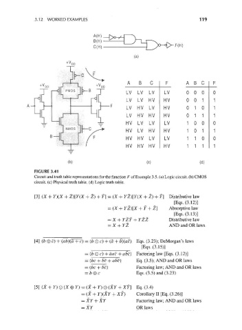
FIGURE 3.41
Circuit and truth table representations for the function F of Example 3.5. (a) Logic circuit, (b) CMOS
circuit, (c) Physical truth table, (d) Logic truth table.
[3] (X + Y)(X + Z)[Y(X + Z) + Y] = (X + YZ)[Y(X + Z) + Y] Distributive law
[Eqs.(3.12)]
= (X + YZ)[X + Y + Z] Absorptive law
[Eqs.(3.13)]
= X + YZY + YZZ Distributive law
= X + YZ AND and OR laws
[4] (b 0 c) + (ab}(a + c} = (b 0 c) + (a + b)(ac) Eqs. (3.23); DeMorgan's laws
[Eqs. (3.15)]
= (b O c) + aac + abc} Factoring law [Eqs. (3.12)]
= (be + bc + abc} Eq. (3.5); AND and OR laws
= (be + be) Factoring law; AND and OR laws
= b 0 c Eqs. (3.5) and (3.23)
[5] (X + Y) O (X 0 F) = (X + 7) O (XY + XY] Eq. (3.4)
= (X + Y)(XY + XY ) Corollary II [Eq. (3.26)]
= XY + XY Factoring law; AND and OR laws
= XY OR laws