
Page 435 - Engineering Digital Design
P. 435
9.3 DETECTION AND ELIMINATION HAZARDS 405
A(H) i
B(H) J
C(H) ;
Y(H) J
Q(H) ; u
BCX(H) J I
Q(H)* ; ^
* Indicates with hazard cover
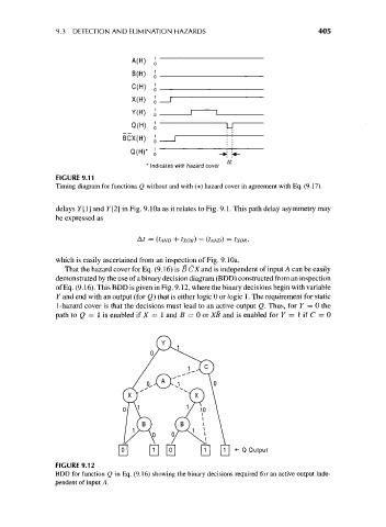
FIGURE 9.11
Timing diagram for functions Q without and with (*) hazard cover in agreement with Eq. (9.17).
delays F[l] and Y[2] in Fig. 9.10a as it relates to Fig. 9.1. This path delay asymmetry may
be expressed as
A? = (tAND + IXOR) — (IAND) = txoR,
which is easily ascertained from an inspection of Fig. 9.10a.
That the hazard cover for Eq. (9.16) is B CX and is independent of input A can be easily
demonstrated by the use of a binary decision diagram (BDD) constructed from an inspection
of Eq. (9.16). This BDD is given in Fig. 9.12, where the binary decisions begin with variable
Y and end with an output (for Q) that is either logic 0 or logic 1. The requirement for static
1-hazard cover is that the decisions must lead to an active output Q. Thus, for 7 = 0 the
path to Q = Us enabled if X = 1 and B = 0 or XB and is enabled for Y = 1 if C = 0
0 0 0 0 111 *~ QOut P u t
FIGURE 9.12
BDD for function Q in Eq. (9.16) showing the binary decisions required for an active output inde-
pendent of input A.