
Page 437 - Engineering Digital Design
P. 437
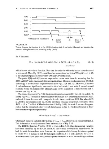
9.3 DETECTION AND ELIMINATION HAZARDS                               407


                         A(H)  J
                         B(H)  5


                                                         ,                   \
                         N(H)*
                                 cates with hazard cover  \                   \
                                                   V  Static 1    At    Static 0 __\
                                                       hazard            hazard
                  FIGURE 9.14
                 Timing diagram for function N in Eq. (9.18) showing static 1 and static 0 hazards and showing the
                 result of adding hazard cover according to Eq. (9.19).


                 for N becomes

                              N = {[(A 0 fi)C] © [(B O D)A] + BCD} • (B + C + D).   (9.19)
                                                               Hazard cover

                 which is now a five-level function. Note that the order in which the hazard cover is added
                 is immaterial. Thus, Eq. (9.19) could have been completed by first ANDing (B + C + D)
                 to the original expression followed by ORing BCD to the result.
                    The paths B[l] and B[2] are not expected to create static hazards, assuming that the
                 XOR and EQV gates have nearly the same path delays. This is a good assumption if CMOS
                 technology is used for their implementation as in Figs. 3.26 and 3.27. However, if the two
                 B path delays are significantly asymmetric, then both static 1 and static 0 hazards would
                 exist and would be eliminated by adding hazard covers in addition to those for the path A
                 hazards (see Fig. 9.13b).
                    The timing diagram in Fig. 9.14 illustrates the results expressed by Eqs. (9.18) and (9.19)
                 and by Fig. 9.13. The static 1-hazard occurs with changes in A under input conditions BCD,
                 and static 0 hazards occur with changes in A under input conditions BCD. But when BCD
                 is ORed to the_expression in Eq. (9.18), the static 1-hazard disappears. Similarly, when
                 BCD = (B + C + D) is ANDed to function N in Eq. (9.18), the static 0 hazards disappear.
                 Notice that the strength of either type of static hazard in Fig. 9.14 is the difference in delay
                 between the two paths expressed by

                                       At = (txoR + tANo) — IAND = txoR>

                 where each hazard is initiated after a delay of (?XOR + ?AND) following a change in input A.
                 This information is easily deduced from an inspection of Fig. 9.13.
                    The BDD for function N in Eq. (9.18) is given in Fig. 9.15. Once the coupled variables
                 have been identified by the LPDD, the BDD can be used to obtain the hazard cover for
                 both the static 1-hazard and static 0-hazard. An inspection of the binary decisions required
                 to render N = 1 indicate a path BC for input condition A = 0 and a path BD for A = 1.
                 When these two input paths are ANDed together the result is BCD, the enabling condition