
Page 441 - Engineering Digital Design
P. 441
9.3 DETECTION AND ELIMINATION HAZARDS 411
K Output
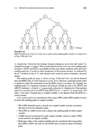
FIGURE 9.18
BDD for function K in Eq. (9.21) that can be used to show enabling paths of input A to output K as
in Figs. 9.16band9.16c.
A, respectively. Notice that the dynamic hazards continue to occur even after input X is
changed from logic 1 to logic 0. This is predictable from Fig. 9.16c, since the enabling paths
for input A, BXYZ and BXYZ, are satisfied in both cases. Input conditions other than these
enabling paths for A would not allow production of the dynamic hazards. As indicated by
the K* waveform in Fig. 9.17, static hazard cover cannot be used to eliminate a dynamic
hazard.
The enabling paths for input A, shown in Figs. 9.16b and 9.16c, can also be deduced
from the BDD in Fig. 9.18 for function K in Eq. (9.21). However, somewhat greater effort
is needed to obtain this information from the BDD owing to its nature. For example, the
enabling paths of A required to produce the dynamic hazards are seen to be ABXYZ and
ABXYZ, yielding K = 0 and K = 1, respectively, with active X. Similarly, for X the enabling
paths of A are observed to be ABXYZ and ABXYZ for K = 1 and K = 0, respectively. The
static 1 and static 0 hazards due to coupled variable A are deduced from the BDD in a
similar manner.
A few points need to be remembered when using LPDD and/or BDD graphical means
to obtain the enabling paths of coupled variables.
• The LPDD should be used to identify the coupled variable and any asymmetry
that may exist in the alternative paths.
• The LPDD or a BDD can be used to deduce the enabling paths for that coupled
variable.
• A BDD must be constructed for each coupled variable, whereas a single LPDD
can be used for all coupled variables.
• Both logic values of the coupled variable must be considered when using either
the LPDD or BDD, but only for the LPDD must account be taken of blocked
paths.